| ||||
> Jensen Healey & Jensen GT Tech > Ignition > Distributor timing and cam belt on a custom high power engine |
| ||||
> Jensen Healey & Jensen GT Tech > Ignition > Distributor timing and cam belt on a custom high power engine |
| Moderated by: Greg Fletcher | Page: 1 2 3   |
|
|||||||||||||
| Distributor timing and cam belt on a custom high power engine | Rate Topic |
| Author | Post |
|---|
| Posted: 01-31-2020 01:10 pm |
|
1st Post |
|
discogodfather Member
|
Hello all, Hope everything is well, after about 12 years I am back and trying to get the Healy running again. Been sitting for 12 years, lol. Going through everything, I decided to change all the belts. This engine is a 907 with lots of performance parts, it was built by a local fellow about 15 years ago and I never got the actually cam specs. This engine is a 2.0 liter but has carillo rods, a knife edged crank, and was designed to spin to 8000. It's a high compression (custom forged pistons) at 9.7 to 1, a cam grind by Elgin (no idea what the specs are though) and it appears to have a set of adjustable cam pulleys (I believe Michael's motorsports used to sell these). The distributor pulley also looks not jensen healey, it's marked Lotus and has a IN and EX hash mark and a kind of squarish main mark. Since none of the factory marks seem to be present I always just marked the relative positions of the cam pulleys and distributor pulley in the past when I replaced the cam belt. I noticed in the factory service manual it says that the distributor pulley mark should face downwards and the rotor should be facing in "the upward position from vertical". My "Lotus" marked distributor pulleys marks don't seem to line up to a damn thing. I just marked it with some paint to help me put it back together correctly, but now I am very interested in proving to myself I know exactly where the rotor should be. Should it face upwards like the factory manual says? Is there any other way to time this thing so I don't feel so in the dark? Right now with the cams aligned and the distributor pulley aligned to wherever I found it the top of the ignition rotor sits at around the 3 o'clock position (when looking from the front of the engine to the back). Take a look at the pics attached and let me know what you think. I also noticed that my old cam marks, when I rotate the engine to TDC on cylinder #1, was off by around 2 teeth. I simply rotated the cams back into alignment. I always dreaded having to degree in these cams, using that MOP stuff, but it appears now might be the time to finally do this. Anyone have some advice or a how to accomplish this? Thanks again, hopefully I will be around and contributing more when this baby gets running again. 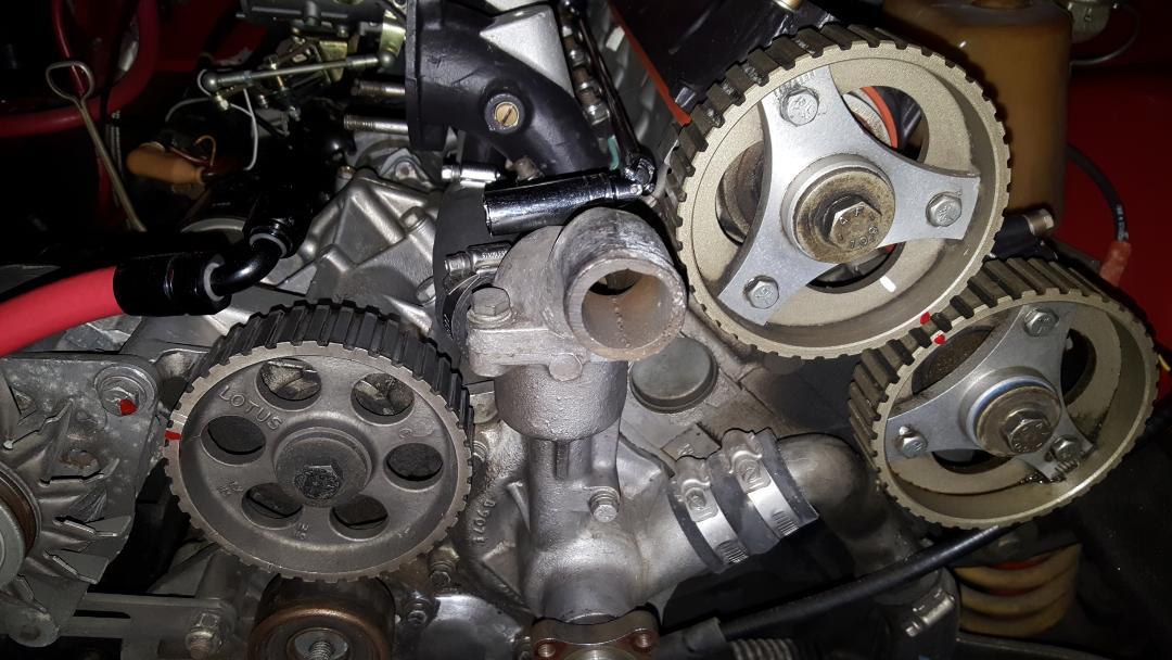 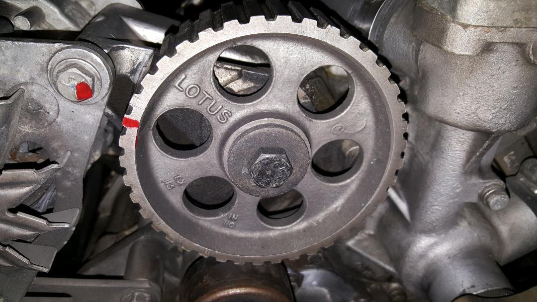 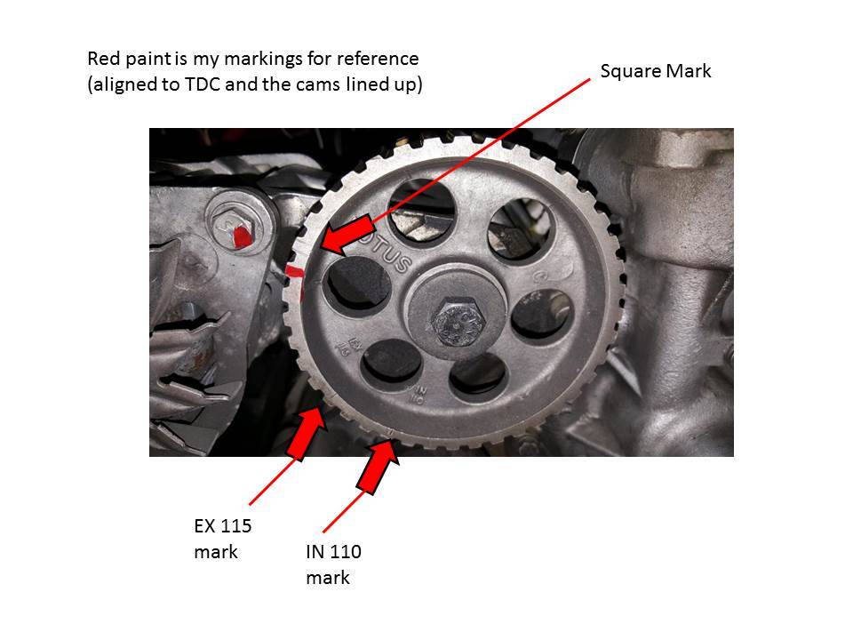
|
||||||||||||||
| |||||||||||||||
| Posted: 02-01-2020 03:41 pm |
|
2nd Post |
|
redracer Member
|
Tim Engel has written extensively about this on the JHPS website, but we'll get you started. First, the position of the ditributor/oil pump sprocket has no correlation to the Intake & Exhaust cam sprockets, which are solely for valve timing whereas the dizzy sprocket is for ignition timing. Assuming you still have points in the dizzy, you would static time this to about 10-15 degrees BTDC(hope you have terminated the vacuum retard capsule?). If you have a Pertronix installed, you would need to eyeball where the rotor would fire the #1 spark plug. As for the cam timing, you would be advised to get a degree wheel & dial indicator(or borrow one) to dial in the variable timing(and remove a cam cover to get the actual cam lobe measuremnt). Ideally, it would be a good idea to make a serious effort to find the engine builder to save you a lot of grief and possibly bent valves. Frankly, after reading your initial statements, I would advise finding someone in your area to change the belt, etc. BEFORE any valves are bent
|
|||||||||||||
| ||||||||||||||
| Posted: 02-01-2020 04:11 pm |
|
3rd Post |
|
discogodfather Member
|
redracer wrote:Tim Engel has written extensively about this on the JHPS website, but we'll get you started. I have the petronix and will try and eyeball where cylinder 1 fires, thanks. Hopefully that gets me into the ballpark. As for degreeing in the cam, I could easily borrow a friends wheel but I am not sure about the process. I understand it would involve getting some fake springs, etc. and using a dial gauge? Anyone have a how to on this for the 907 somewhere? Since I am not sure of the cam grind, would I be wasting my time trying to degree it in without that info? Unfortunately I think the engine builder has moved on or maybe passed on, it's been 20+ years. I haven't had any luck getting in touch with the previous owner either. I'm glad I went to the trouble of changing the cam belt because my tensioner was nearly completely shot. The pulley was domed and the new bearing I got from Greg pushed through without any pressure and you could slide the bearings through the pulley with ease. Still trying to figure out a remedy for this, sent Qwerty a PM. BTW, which way does the engine turn when running, looking from the front of the engine? Sheesh, I knew this would be a big project!
|
||||||||||||||
| |||||||||||||||
| Posted: 02-01-2020 05:49 pm |
|
4th Post |
|
redracer Member
|
The engine rotates clockwise(""CW"). Frankly, this is not that big of a job and again I would suggest enlisting the aid of someone locally.
|
|||||||||||||
| ||||||||||||||
| Posted: 02-01-2020 06:42 pm |
|
5th Post |
|
discogodfather Member
|
redracer wrote:The engine rotates clockwise(""CW"). Frankly, this is not that big of a job and again I would suggest enlisting the aid of someone locally. I have degreed in a few cams years ago, thinking about it has brought back some memories. I even found my old degree wheel. If I found lobe centers, determined lift, and at least determined when valves were opening and closing, could I get a better idea of how these cams should be phased? I have a dial indicator and the time, I also found some of Tim Engel's writings on the subject. Also found a pretty good writeup on a Lotus forum. But they all seem to start with a known cam. As I understand it the venier adjustments on the pulleys are for fine tuning, is that correct? Forgive my ignorance but this has already been very helpful!
|
||||||||||||||
| |||||||||||||||
| Posted: 02-01-2020 09:56 pm |
|
6th Post |
|
redracer Member
|
Correct(the verniers on the cam sprockets). I personally do not know of the different cams(eg. 107, 105, etc) for their grinds, so hopefully Tim will jump in(although I do believe he may have already posted them); Here's something i found in "SEARCH" for "Tim Engel, cam: http://www.jensenhealey.com/forums/view_topic.php?id=746&forum_id=2&highlight=Tim+Engel%2C+cam
|
|||||||||||||
| ||||||||||||||
| Posted: 02-02-2020 01:48 am |
|
7th Post |
|
Esprit2 Member
|
discogodfather wrote:Since none of the factory marks seem to be present I always just marked the relative positions of the cam pulleys and distributor pulley in the past when I replaced the cam belt.If you didn't do the intitial installation, and set the adjustable pulleys yourself, and if you don't even know which cams are installed, then you are putting a heck of a lot of blind faith in whomever did the work. Marking the pulleys, then putting them back where you found them may simply be replicating someone else's mistakes. discogodfather wrote: (Snip)... a cam grind by Elgin (no idea what the specs are though)...:-/ As a first step, you need to figure out what the cam specs are. Without that, you're just groping in the dark and wasting time. Call Elgin Cams, and talk with Dema Elgin. Ask him where to find an identifying mark on the cams, then find the marks on both cams separately (don't presume they're the same), and report back to Dema. With the cam IDs, Dema should be able to give you the specs. Unfortunately, he usually quotes the timing specs in a format that is more confusing than helpful. Well... to me anyway. Good luck with that. Failing that, get a degree wheel and two dial indicators... one on the #1 piston to find TDC, and one on the tappet (perpendicular to it). Don't try to follow the cam lobe... follow the TAPPET. Of course, valve clearance will mess with that reading, so first shim the clearance to a slightly negative value. Then carefully/ accurately determine the following: . . . . . . . . . . . . . . Intake . . . Exhaust Lift (inch) . . . . . . . 0.???" . . . 0.???" Int. Opens, BTDC . . ??° . . . . . ??° Int. Closes, ABDC . . ??° . . . . . ??° Exh Opens BBDC. . . ??° . . . . . ??° Exh Closes ATDC. . . ??° . . . . . ??° Overlap . . . . . . . . . ??° . . . . . ??°, calculate as follows: Duration. . . . . . . . ???°. . . . . ???°, calculate as follows: MOP. . . . . . . . . . . ???°. . . . . ???°, calculate as follows: Overlap = Int Opens + Exhaust Closes Int. Duration = Int. Opens + 180° + Int. Closes Ext Duration = Exh Opens + 180° + Exh Closes MOP = [(Int. Opens, BTDC + Int. Closes, ABDC + 180°)/2] - Int Opens, BTDC MOP = [(Exh Opens, BBDC + Exh Closes, ATDC + 180°)/2] - Exh Closes, ATDC LOTUS Cam ID. . . . . C. . . . . . . D . . . . . . . E . . . . . . . 107. . . . . 104 . . . . . Elgin something or other Int. Opens, BTDC . . 26° . . . . . 25° . . . . . 27.5° . . . . . 22° . . . . . 32° . . . . . ??° Int. Closes, ABDC . . 66° . . . . . 65° . . . . . 52.5° . . . . . 50° . . . . . 60° . . . . . ??° Exh Opens BBDC. . . 66° . . . . . 65° . . . . . 52.5° . . . . . 50° . . . . . 60° . . . . . ??° Exh Closes ATDC. . . 26° . . . . . 25° . . . . . 27.5° . . . . . 22° . . . . . 32° . . . . . ??° Overlap . . . . . . . . . 52° . . . . . 50° . . . . . 55°. . . . . . . 44° . . . . . 64° . . . . . ??° Duration. . . . . . . . 272° . . . . 270° . . . . 260°. . . . . . 252°. . . . . 272°. . . . . ???° MOP. . . . . . . . . . . 110° . . . . 110° . . . . 102.5°. . . . . 104° . . . . 104°. . . . . ???° The MOP is different for each grind profile, depending upon the opening and closing events. That's not debatable. Then the correct pulley for that cam must have the keyway cut in the bore at an angular location that supports that MOP. Adjustable pulleys allow you to buy a generic part, and set it to the correct MOP... ie, it's universal. It only becomes a "tuning" tool if you seriously know what the heck you're doing. Failing that, stick with the default values as calculated above. All the Lotus values follow those calculations. discogodfather wrote: (Snip)... I noticed in the factory service manual it says that the distributor pulley mark should face downwards and the rotor should be facing in "the upward position from vertical".The Auxiliary Pulley timing dot is 'roughly' across the pulley from the two cam timing marks. If you don't see it on the front of your Aux pulley, then look on the back side. If you see it there, then the pulley is on backwards. You can still time the distributor, but you'll have to wing it instead of following the book. Do you have a non-emissions distributor WITHOUT an external vacuum retard capsule, or an emissions distributor WITH one? Functionally, the distributor doesn't care how the auxiliary pulley is timed, or which way the rotor is pointing. You can loosen the clamp and rotate the distributor body as required to align it with the rotor at the desired Static Timing (14°-15° BTDC). But in the real world, there are practical factors. In some orientations, one clip that holds the distributor cap on might end up facing the engine block, in which case it may be difficult to impossible to release. OR, the emissions vacuum capsule will only fit in the gap between the oil filter and the bottom of the front carb. The Aux timing dot is simply a 'safe' location were all the bits fit without interfering with anything else. With that in mind, if you need help timing the ignition, let us know. Regards, Tim Engel Last edited on 02-02-2020 03:07 am by Esprit2 |
||||||||||||||
| |||||||||||||||
| Posted: 02-02-2020 03:21 am |
|
8th Post |
|
Esprit2 Member
|
Disco, If this project exceeds your reach, you're fortunate to be ~close to Spencer's Motorsports. Barry Spencer can time a 907 with his eyes closed, in a dark room. But he would still need to know the specs for the cams that are installed. Barry Spencer - Owner 5701 State Farm Dr #11 Rohnert Park, CA 94928 (north of Petaluma) (855) 456-8873 Spencersmotorsports@gmail.com http://www.spencersmotorsports.com/index.html Regards, Tim Engel
|
|||||||||||||
| ||||||||||||||
| Posted: 02-02-2020 05:11 am |
|
9th Post |
|
Esprit2 Member
|
discogodfather wrote:I have the petronix and will try and eyeball where cylinder 1 fires, thanks. Hopefully that gets me into the ballpark.FYI, the Pertronix and 123 distributors do not have the internal lip seal that Lucas installed for Lotus 907's horizontal installation. It's common for them to leak. Regards, Tim Engel
|
||||||||||||||
| |||||||||||||||
| Posted: 02-02-2020 05:36 am |
|
10th Post |
|
discogodfather Member
|
Thanks much Tim, I took Dema Elgin's high performance engine class 25 years ago at Skyline college here locally and learned all about cams, then forgot it promptly. I can still hear Dema yelling at me about lobe centers. I'll look into it a bit more deeply and try and see what kind of ID marks are on the cam and then contact Elgin to see what's up like you said. I think my distributor is a centrifugal advance with the petronix module in it but I have to check again. Again, thanks for all this amazing information. I think I will give Barry Spencer a call on Monday.
|
|||||||||||||
| ||||||||||||||
| Posted: 02-02-2020 07:22 am |
|
11th Post |
|
Esprit2 Member
|
discogodfather wrote:I can still hear Dema yelling at me about lobe centers.What Lotus calls MOP (Maximum Opening Point), we on this side of the pond call 'Lobe Centers'. Same thing. discogodfather wrote: I think my distributor is a centrifugal advance with the petronix module in it but I have to check again.Original Lucas? Just with a Pertronix kit installed? Then it has the internal lip-seal. The original Pertronix Ignitor was magnetic, and can still be static timed. The Pertronix Ignitor II & III use a Hall Effect sensor, and have to be moving at 200 rpm before they work... so no static timing. For them, you eyeball the timing close enough for the engine to start, then use a strobe to accurately set the timing. discogodfather wrote: I think I will give Barry Spencer a call on Monday.If you do call Barry, tell him Tim said "Hi". There's no discount value in there... just sayin' "Hi". Regards, Tim Engel
|
||||||||||||||
| |||||||||||||||
| Posted: 02-06-2020 10:16 am |
|
12th Post |
|
discogodfather Member
|
Finally got around to pulling my distributor yesterday. Seems like it's a Lucas 25D that's had its vacuum advance converted to a Centrifical. It has the Petronix ignitor. The unit has been sitting for a decade and seems a bit loose and grungy. I found an outfit in the UK called PowerSpark that sells Luca 23D and 43D units that are new and reasonably priced at around $75, will these work? I contacted them and Tom said I could use either the 23D or the 43D top mount style. They seem to have an electronic igniter built into them? The cost to rebuild through JHPS seems more like in the $300 range. I know not use the ballast resistor in coils that are 3 ohms, is that correct? The ballast resistor is only used with 1.5 ohm versions? I'm still wondering what's going on with my wiring, but that's the next step. 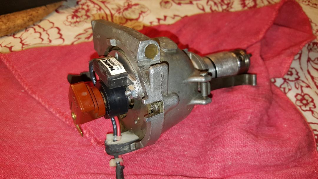 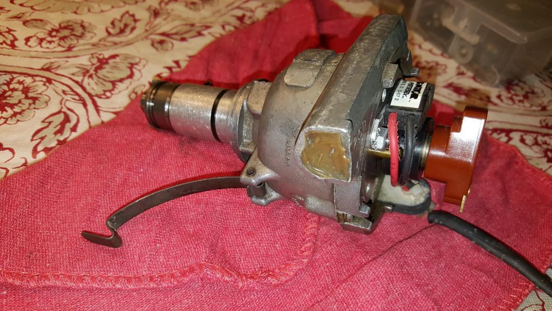 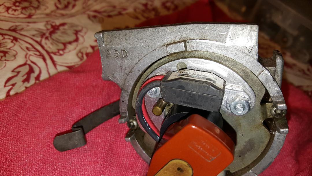
|
|||||||||||||
| ||||||||||||||
| Posted: 02-08-2020 03:19 am |
|
13th Post |
|
Tom Bradley Member
|
discogodfather wrote:Finally got around to pulling my distributor yesterday. Seems like it's a Lucas 25D that's had its vacuum advance converted to a Centrifical. The original distributor was a 25D that had centrifugal advance and vacuum retard (at least with the Stromberg carbs). This one looks like it had the vacuum retard removed by the PO, which is very common. If this is the original distributor, then it also had some extra stuff inside the shaft that kept oil from leaking out when it was mounted sideways in the 907 engine. As far as I know, nothing else out there has that. It looks to me to be in good shape, so I would say keep it. As long as it is not leaking oil or the advance is not working, it should not need rebuilding. Just replace the o-ring and lubricate the advance mechanism if it seems to need it. Then check that the total advance is 17 degrees going from 1000 to 2500 RPM. It has the Petronix ignitor. The ballast resistor and higher-ohm coil was to keep the original mechanical points from burning out. If you have a Pertronix 2 or 3 ignition, then you can go to as low as 0.6 ohm coil and get rid of the ballast resistor. If you have the Pertronix 1 version you probably need to keep the ballast resistor and a higher-resistance coil. Since I have the 2, I am not sure the exact numbers. If you check their web site, they should have specs for this. If you can afford it, I would switch to the 2 if it is a 1. Just fewer potential problems. One thing to keep in mind is that, if you have the original tachometer setup, going to a low resistance coil will probably make the tach read high. So be sure to use an automotive engine analyser with a tachometer function to do the tune-up.
|
||||||||||||||
| |||||||||||||||
| Posted: 02-10-2020 11:28 pm |
|
14th Post |
|
Esprit2 Member
|
At a glance, the obvious difference between the early 23D4 / 25D4 and the later 43D4 / 45D4 is that the head & cap diameters were smaller on the early models, and larger on the later ones. The 23D4 / 25D4 are too small to accept the later Ignitor II & Ignitor III. Well... I do know of one person who installed an Ignitor II into a 23D4, but he had to grind away at the amplifier's housing, reducing it's "Outside" radius until if fit into the 23 distributor head. However, doing that immediately voids any Pertronix warranty, so you go there on your own. The Pertronix in the photos is their first, basic Ignitor. It's a "points replacer", and little more. It is not a performance upgrade, and it cannot handle hotter coils. The basic Ignitor has no internal safeguards, and is both polarity and temperature sensitive. Know what you're doing before you install the Ignitor, and make no mistakes. It has "ZERO" tolerance for reverse polarity, and it will instantly and permanently fry if you get the polarity wrong on any one wire. You cannot undo a backward polarity connection fast enough to save it... instantly zap-dead, and it's permanently done. Use it with the car's OEM "breaker points" ignition coil and spark plug gap that would have been used with the breaker points. It requires more voltage to jump a larger spark plug gap. If you increase the plug gap for performance, then the high-tension side of the system will automatically run at a higher voltage. Increase the gap enough, and you'll need an aftermarket hotter coil to keep up with firing the plugs. For the basic Ignitor, keep the plug gaps at the car's original "breaker points" spark-plug gap... no greater. Either larger plug gaps or hotter coils, or both will cause the basic Ignitor to over-heat and fry. Using a coil that is hotter than the OEM "breaker points" coil will result in a higher current draw that will cause the basic Ignitor to over-heat and fry. Acrid smelling, smoldering, permanently fried, "Dead". It has no internal temp sensor to switch itself off when it gets hot, it just fries itself to a crisp and you buy a new one. The ignition system goes on & off as the engine runs. Picture the breaker points... open-closed-open-closed. They close to turn on and charge the coil. Then they open to disconnect the coil so the magnetic field colapses through the coil windings and fires the spark. So, in normal operation, the ignition runs at some Duty Cycle that's (??) closer to 50% than 100%. While the engine is running normally, with an OEM "points" coil, the Ignitor doesn't get hot enough to fry. However, if you turn on the ignition switch without starting the engine (oh, say, to debug a wiring problem), then it's a lottery... or roulette as to whether the ignition circuit will be On with a 100% duty cycle (points closed), or off (points open). IF the engine's position is such that the ignition is on (ie points closed/ amp 'on'), then normal 12 volt/ 'points' coil current running through the Pertronix full time will over-heat and fry the Ignitor's amp in about 10-15 minutes... depending upon the coil's internal resistance (Re). Far less time with a 'hot' coil. As above, once fried it's dead and not coming back. If you're going to work on your car with the ignition switch on, then either: 1) Disconnect the ignition coil, or... 2) Get your ducks all lined up, switch on only when ready, work fast, and switch off in less than 10 minutes, or... 3) Use a volt-ohm meter to determine if the ignition coil is 'ON' when the ignition switch is 'on'. If yes, then rotate the engine until the ignition switches off, and work with the engine in that position. If you're static timing the engine, then you may not have that option. The later, more expensive Ignitor II & III both have built-in safeguards against reverse polarity and thermal overload. You're protected from making a simple mistake and frying your brand new ignition system. The II & III can also handle high performance coils without melting down, and Pertronix claims they're happier with the hotter, "FlameThrower" coils. Regards, Tim Engel
|
|||||||||||||
| ||||||||||||||
| Posted: 02-10-2020 11:32 pm |
|
15th Post |
|
Esprit2 Member
|
It's not unusual for installing an electronic ignition system to cause a tach to stop functioning correctly. The needle may still move, but the indicated RPM may be way off. Pertronix sells a Tach Adapter Module. I've not used one, and can't say if it will work with a Smiths, Jaeger or JH tach. Regards, Tim Engel Last edited on 02-10-2020 11:34 pm by Esprit2 |
||||||||||||||
| |||||||||||||||
| Posted: 02-11-2020 12:42 am |
|
16th Post |
|
discogodfather Member
|
Esprit2 wrote:
I think I might have committed all of the list to things not to do with the ignitor including reverse the polarity, turn the ignition on for long periods of time (when I was doing some electrical diagnosis elsewhere) and then used a flamethrower coil. Then I wondered why the car was running so badly, misses, bad idle, popping, etc. Feels bad because I thought it was the carbs, two older Italian 45 DCOE's. I sold them and bought two new Spanish Webers. I miss the Italian ones! Oh well, live and learn. Should have read more about it to begin with. Going to go back to points for the time being with an original coil and the ballast resistor. Powerspark, the UK company I contacted, has a version of the 43D that is "high energy" that uses some electronic ignition module that can be used with a very low resistance coil. It's not bad at a little over $100 shipped to the USA. It seems to have the o-ring on the shaft. I know I have read a bit about how bad the Lucas copies are, but this seemed like an interesting option.
|
|||||||||||||
| ||||||||||||||
| Posted: 02-11-2020 06:56 am |
|
17th Post |
|
Esprit2 Member
|
discogodfather wrote:Powerspark, the UK company I contacted, has a version of the 43D (Snip)... They all have an O-ring around the shaft housing... on the outside, where it slips into the oil pump housing. It's the Lotus-only internal lip-seal that is missing. It should be inside the housing. If you were to remove everything from inside the 'head' of the housing, you would see a small lip seal around the hole in the floor where the shaft would pass through. In all other Lucas distributors and clones, there would be no seal, just an open gap between the shaft OD and housing ID. That's a path for oil to flow from the engine into the distributor's head, and from there to leak out onto the side of the engine block. Regards, Tim Engel
|
||||||||||||||
| |||||||||||||||
| Posted: 02-12-2020 05:46 am |
|
18th Post |
|
discogodfather Member
|
Esprit2 wrote: I received my $100 43D from Powerspark, I thought it would be interesting to check it out and compare with the stock unit. What I see taking them apart (also took my 25D apart) is that there isn't much difference on the shafts. The 25D Lucas unit has what appears to be a thin spiral cut channel on the side of it, and the cutout seems to be in a slightly different place. All the seals and bushings are similar. The centrifugal advance assemblies are a lot different. Could it be this 25D I have is not a special Lotus unit? I don't think I had any oil leaks, at least the inside of the distributor is clean, nothing in the cap. Maybe I am looking in the wrong place? The PowerSpark unit has a pretty robust looking electronic switch unit, it looks like a beast- this is the one they claim has the capability of a low resistance coil (like .7 ohms) and 3x the spark. The old Lucas 25D I have has a 41584 A number followed by a 48 and 74. 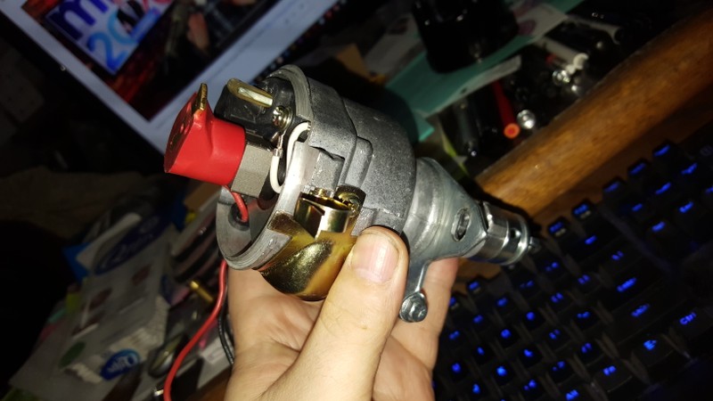 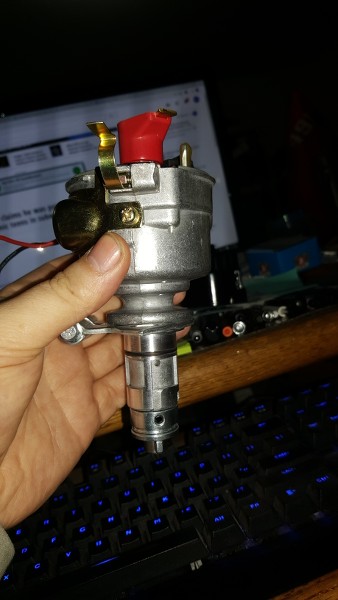 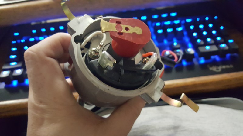 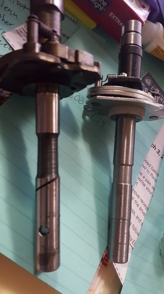 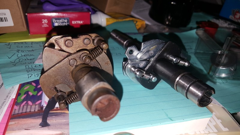 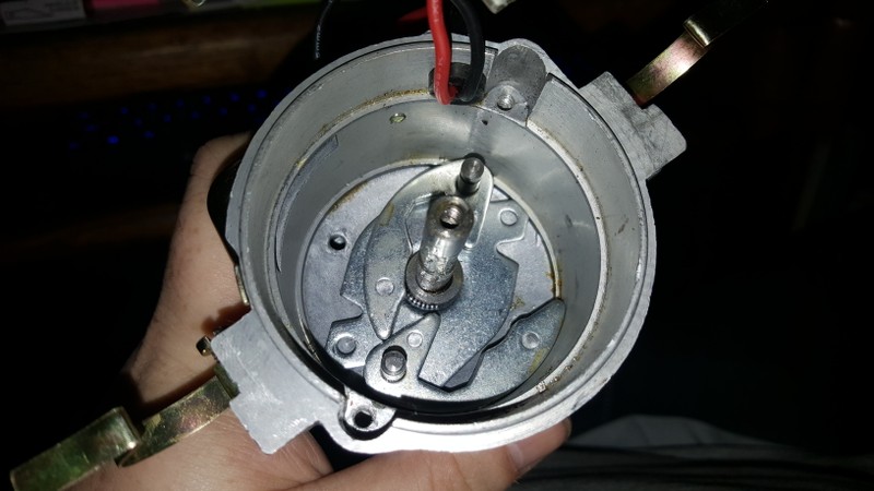 Last edited on 02-12-2020 05:46 am by discogodfather |
|||||||||||||
| ||||||||||||||
| Posted: 02-12-2020 05:57 am |
|
19th Post |
|
discogodfather Member
|
Just picked up on this difference after re-reading Tim's explanation- there is a black metal ring on the bottom of the floor of the distributor housing. It's not much of a seal though, it looks to be worn well in.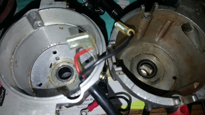
|
||||||||||||||
| |||||||||||||||
| Posted: 02-12-2020 08:11 pm |
|
20th Post |
|
Tom Bradley Member
|
discogodfather wrote:What I see taking them apart (also took my 25D apart) is that there isn't much difference on the shafts. The 25D Lucas unit has what appears to be a thin spiral cut channel on the side of it, and the cutout seems to be in a slightly different place. All the seals and bushings are similar. The centrifugal advance assemblies are a lot different. I also pulled one of my distributors apart and it looks the same as yours. I think the spiral acts as a pump to push the oil back towards the engine. As long as you are not getting any oil inside the distributor it should be OK. The centrifugal advance on the JH was made specific for the Lotus engine. It is unlikely that a general purpose distributor like Powerspark will be the same. If you use it, your car will probably run OK, but may not have the performance or smooth acceleration that you will get with the original. Personally I think that going back to mechanical points is a bad idea. These are much more prone to problems than even a basic solid state switch. The electronic switches in the Ignitor 1 are unlikely to be bad if the car was running at all. When these go bad, they usually die completely, not get unreliable. If the car was running poorly it was more likely caused by other things like a bad distributor cap or poor electrical connections somewhere. BTW, Pertronix does make an Ignitor 2 specifically for the 25D4 distributor. That is what I have on mine and has been working well for several years now. It is available from Amazon: https://www.amazon.com/Pertronix-9LU-142A-Ignitor-Lucas-Cylinder/dp/B00AWQRJRO
|
|||||||||||||
| ||||||||||||||
| Current time is 01:40 am | Page: 1 2 3   |
| > Jensen Healey & Jensen GT Tech > Ignition > Distributor timing and cam belt on a custom high power engine | Top |