> Jensen Healey & Jensen GT Tech > Ignition > Distributor timing and cam belt on a custom high power engine |
> Jensen Healey & Jensen GT Tech > Ignition > Distributor timing and cam belt on a custom high power engine |
| Moderated by: Greg Fletcher | ||
| Author | Post | |||||||||
|---|---|---|---|---|---|---|---|---|---|---|
|
discogodfather Member
|
Hello all, Hope everything is well, after about 12 years I am back and trying to get the Healy running again. Been sitting for 12 years, lol. Going through everything, I decided to change all the belts. This engine is a 907 with lots of performance parts, it was built by a local fellow about 15 years ago and I never got the actually cam specs. This engine is a 2.0 liter but has carillo rods, a knife edged crank, and was designed to spin to 8000. It's a high compression (custom forged pistons) at 9.7 to 1, a cam grind by Elgin (no idea what the specs are though) and it appears to have a set of adjustable cam pulleys (I believe Michael's motorsports used to sell these). The distributor pulley also looks not jensen healey, it's marked Lotus and has a IN and EX hash mark and a kind of squarish main mark. Since none of the factory marks seem to be present I always just marked the relative positions of the cam pulleys and distributor pulley in the past when I replaced the cam belt. I noticed in the factory service manual it says that the distributor pulley mark should face downwards and the rotor should be facing in "the upward position from vertical". My "Lotus" marked distributor pulleys marks don't seem to line up to a damn thing. I just marked it with some paint to help me put it back together correctly, but now I am very interested in proving to myself I know exactly where the rotor should be. Should it face upwards like the factory manual says? Is there any other way to time this thing so I don't feel so in the dark? Right now with the cams aligned and the distributor pulley aligned to wherever I found it the top of the ignition rotor sits at around the 3 o'clock position (when looking from the front of the engine to the back). Take a look at the pics attached and let me know what you think. I also noticed that my old cam marks, when I rotate the engine to TDC on cylinder #1, was off by around 2 teeth. I simply rotated the cams back into alignment. I always dreaded having to degree in these cams, using that MOP stuff, but it appears now might be the time to finally do this. Anyone have some advice or a how to accomplish this? Thanks again, hopefully I will be around and contributing more when this baby gets running again. 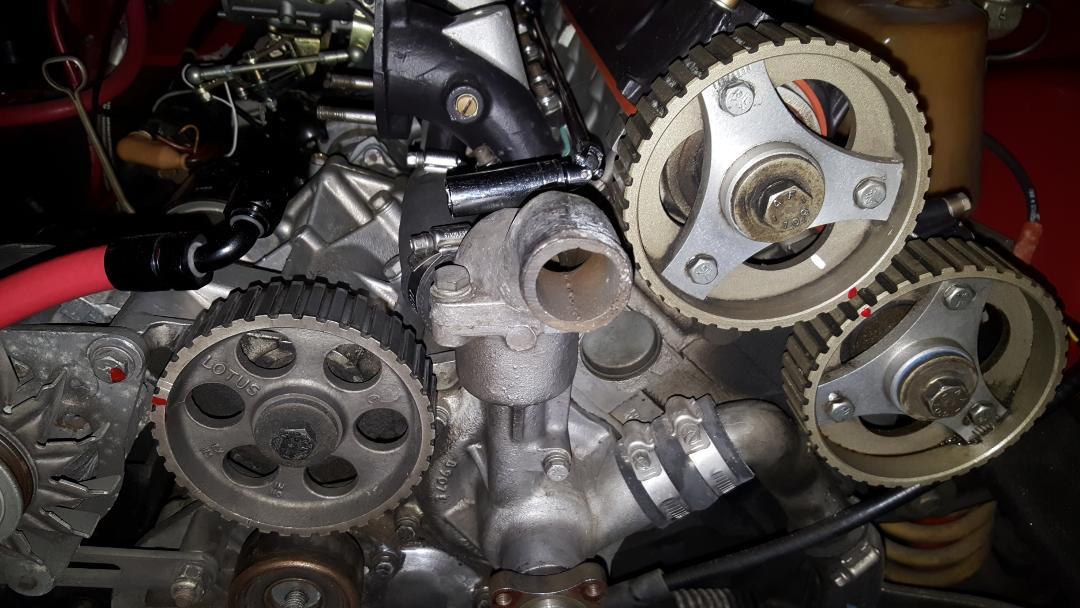 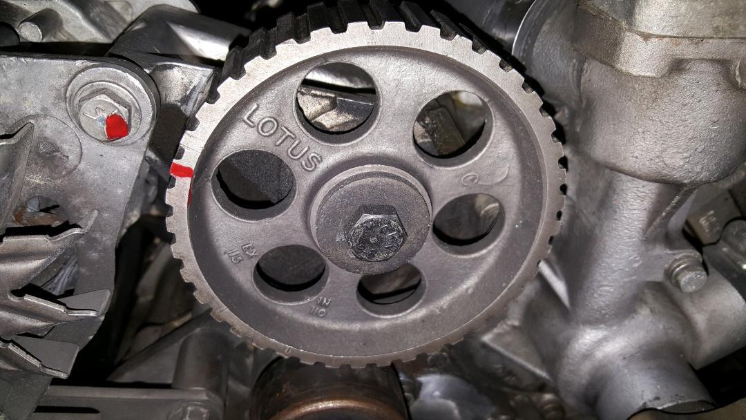 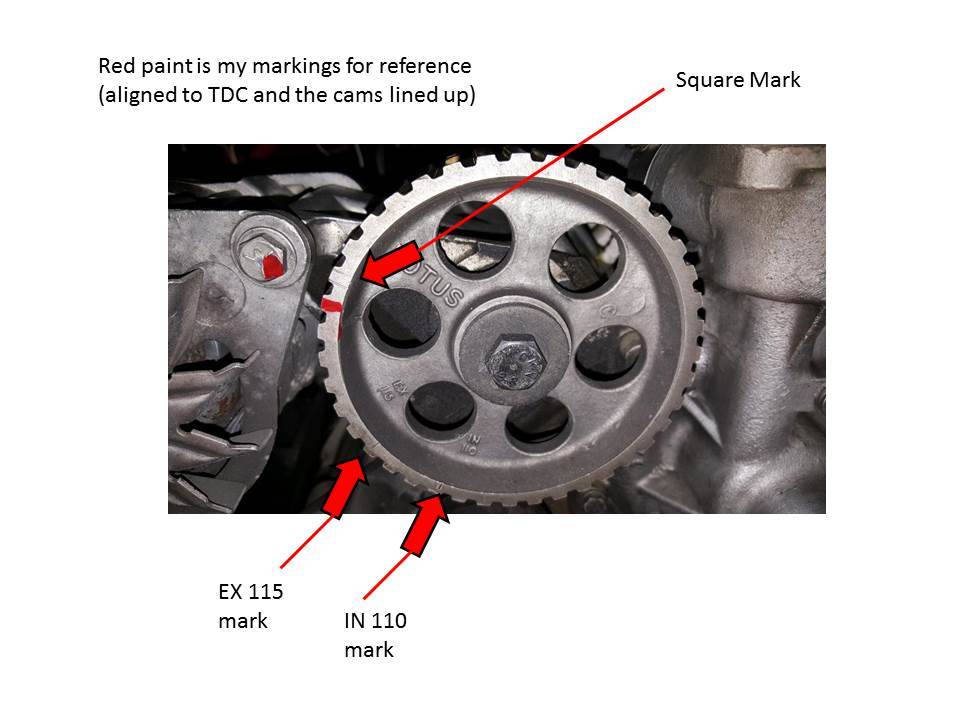 |
|||||||||
|
redracer Member
|
Tim Engel has written extensively about this on the JHPS website, but we'll get you started. First, the position of the ditributor/oil pump sprocket has no correlation to the Intake & Exhaust cam sprockets, which are solely for valve timing whereas the dizzy sprocket is for ignition timing. Assuming you still have points in the dizzy, you would static time this to about 10-15 degrees BTDC(hope you have terminated the vacuum retard capsule?). If you have a Pertronix installed, you would need to eyeball where the rotor would fire the #1 spark plug. As for the cam timing, you would be advised to get a degree wheel & dial indicator(or borrow one) to dial in the variable timing(and remove a cam cover to get the actual cam lobe measuremnt). Ideally, it would be a good idea to make a serious effort to find the engine builder to save you a lot of grief and possibly bent valves. Frankly, after reading your initial statements, I would advise finding someone in your area to change the belt, etc. BEFORE any valves are bent |
|||||||||
|
discogodfather Member
|
redracer wrote:Tim Engel has written extensively about this on the JHPS website, but we'll get you started. I have the petronix and will try and eyeball where cylinder 1 fires, thanks. Hopefully that gets me into the ballpark. As for degreeing in the cam, I could easily borrow a friends wheel but I am not sure about the process. I understand it would involve getting some fake springs, etc. and using a dial gauge? Anyone have a how to on this for the 907 somewhere? Since I am not sure of the cam grind, would I be wasting my time trying to degree it in without that info? Unfortunately I think the engine builder has moved on or maybe passed on, it's been 20+ years. I haven't had any luck getting in touch with the previous owner either. I'm glad I went to the trouble of changing the cam belt because my tensioner was nearly completely shot. The pulley was domed and the new bearing I got from Greg pushed through without any pressure and you could slide the bearings through the pulley with ease. Still trying to figure out a remedy for this, sent Qwerty a PM. BTW, which way does the engine turn when running, looking from the front of the engine? Sheesh, I knew this would be a big project! |
|||||||||
|
redracer Member
|
The engine rotates clockwise(""CW"). Frankly, this is not that big of a job and again I would suggest enlisting the aid of someone locally. |
|||||||||
|
discogodfather Member
|
redracer wrote:The engine rotates clockwise(""CW"). Frankly, this is not that big of a job and again I would suggest enlisting the aid of someone locally. I have degreed in a few cams years ago, thinking about it has brought back some memories. I even found my old degree wheel. If I found lobe centers, determined lift, and at least determined when valves were opening and closing, could I get a better idea of how these cams should be phased? I have a dial indicator and the time, I also found some of Tim Engel's writings on the subject. Also found a pretty good writeup on a Lotus forum. But they all seem to start with a known cam. As I understand it the venier adjustments on the pulleys are for fine tuning, is that correct? Forgive my ignorance but this has already been very helpful! |
|||||||||
|
redracer Member
|
Correct(the verniers on the cam sprockets). I personally do not know of the different cams(eg. 107, 105, etc) for their grinds, so hopefully Tim will jump in(although I do believe he may have already posted them); Here's something i found in "SEARCH" for "Tim Engel, cam: http://www.jensenhealey.com/forums/view_topic.php?id=746&forum_id=2&highlight=Tim+Engel%2C+cam |
|||||||||
|
Esprit2 Member
|
discogodfather wrote:Since none of the factory marks seem to be present I always just marked the relative positions of the cam pulleys and distributor pulley in the past when I replaced the cam belt.If you didn't do the intitial installation, and set the adjustable pulleys yourself, and if you don't even know which cams are installed, then you are putting a heck of a lot of blind faith in whomever did the work. Marking the pulleys, then putting them back where you found them may simply be replicating someone else's mistakes. discogodfather wrote: (Snip)... a cam grind by Elgin (no idea what the specs are though)...:-/ As a first step, you need to figure out what the cam specs are. Without that, you're just groping in the dark and wasting time. Call Elgin Cams, and talk with Dema Elgin. Ask him where to find an identifying mark on the cams, then find the marks on both cams separately (don't presume they're the same), and report back to Dema. With the cam IDs, Dema should be able to give you the specs. Unfortunately, he usually quotes the timing specs in a format that is more confusing than helpful. Well... to me anyway. Good luck with that. Failing that, get a degree wheel and two dial indicators... one on the #1 piston to find TDC, and one on the tappet (perpendicular to it). Don't try to follow the cam lobe... follow the TAPPET. Of course, valve clearance will mess with that reading, so first shim the clearance to a slightly negative value. Then carefully/ accurately determine the following: . . . . . . . . . . . . . . Intake . . . Exhaust Lift (inch) . . . . . . . 0.???" . . . 0.???" Int. Opens, BTDC . . ??° . . . . . ??° Int. Closes, ABDC . . ??° . . . . . ??° Exh Opens BBDC. . . ??° . . . . . ??° Exh Closes ATDC. . . ??° . . . . . ??° Overlap . . . . . . . . . ??° . . . . . ??°, calculate as follows: Duration. . . . . . . . ???°. . . . . ???°, calculate as follows: MOP. . . . . . . . . . . ???°. . . . . ???°, calculate as follows: Overlap = Int Opens + Exhaust Closes Int. Duration = Int. Opens + 180° + Int. Closes Ext Duration = Exh Opens + 180° + Exh Closes MOP = [(Int. Opens, BTDC + Int. Closes, ABDC + 180°)/2] - Int Opens, BTDC MOP = [(Exh Opens, BBDC + Exh Closes, ATDC + 180°)/2] - Exh Closes, ATDC LOTUS Cam ID. . . . . C. . . . . . . D . . . . . . . E . . . . . . . 107. . . . . 104 . . . . . Elgin something or other Int. Opens, BTDC . . 26° . . . . . 25° . . . . . 27.5° . . . . . 22° . . . . . 32° . . . . . ??° Int. Closes, ABDC . . 66° . . . . . 65° . . . . . 52.5° . . . . . 50° . . . . . 60° . . . . . ??° Exh Opens BBDC. . . 66° . . . . . 65° . . . . . 52.5° . . . . . 50° . . . . . 60° . . . . . ??° Exh Closes ATDC. . . 26° . . . . . 25° . . . . . 27.5° . . . . . 22° . . . . . 32° . . . . . ??° Overlap . . . . . . . . . 52° . . . . . 50° . . . . . 55°. . . . . . . 44° . . . . . 64° . . . . . ??° Duration. . . . . . . . 272° . . . . 270° . . . . 260°. . . . . . 252°. . . . . 272°. . . . . ???° MOP. . . . . . . . . . . 110° . . . . 110° . . . . 102.5°. . . . . 104° . . . . 104°. . . . . ???° The MOP is different for each grind profile, depending upon the opening and closing events. That's not debatable. Then the correct pulley for that cam must have the keyway cut in the bore at an angular location that supports that MOP. Adjustable pulleys allow you to buy a generic part, and set it to the correct MOP... ie, it's universal. It only becomes a "tuning" tool if you seriously know what the heck you're doing. Failing that, stick with the default values as calculated above. All the Lotus values follow those calculations. discogodfather wrote: (Snip)... I noticed in the factory service manual it says that the distributor pulley mark should face downwards and the rotor should be facing in "the upward position from vertical".The Auxiliary Pulley timing dot is 'roughly' across the pulley from the two cam timing marks. If you don't see it on the front of your Aux pulley, then look on the back side. If you see it there, then the pulley is on backwards. You can still time the distributor, but you'll have to wing it instead of following the book. Do you have a non-emissions distributor WITHOUT an external vacuum retard capsule, or an emissions distributor WITH one? Functionally, the distributor doesn't care how the auxiliary pulley is timed, or which way the rotor is pointing. You can loosen the clamp and rotate the distributor body as required to align it with the rotor at the desired Static Timing (14°-15° BTDC). But in the real world, there are practical factors. In some orientations, one clip that holds the distributor cap on might end up facing the engine block, in which case it may be difficult to impossible to release. OR, the emissions vacuum capsule will only fit in the gap between the oil filter and the bottom of the front carb. The Aux timing dot is simply a 'safe' location were all the bits fit without interfering with anything else. With that in mind, if you need help timing the ignition, let us know. Regards, Tim Engel Last edited on 02-02-2020 03:07 am by Esprit2 |
|||||||||
|
Esprit2 Member
|
Disco, If this project exceeds your reach, you're fortunate to be ~close to Spencer's Motorsports. Barry Spencer can time a 907 with his eyes closed, in a dark room. But he would still need to know the specs for the cams that are installed. Barry Spencer - Owner 5701 State Farm Dr #11 Rohnert Park, CA 94928 (north of Petaluma) (855) 456-8873 Spencersmotorsports@gmail.com http://www.spencersmotorsports.com/index.html Regards, Tim Engel |
|||||||||
|
Esprit2 Member
|
discogodfather wrote:I have the petronix and will try and eyeball where cylinder 1 fires, thanks. Hopefully that gets me into the ballpark.FYI, the Pertronix and 123 distributors do not have the internal lip seal that Lucas installed for Lotus 907's horizontal installation. It's common for them to leak. Regards, Tim Engel |
|||||||||
|
discogodfather Member
|
Thanks much Tim, I took Dema Elgin's high performance engine class 25 years ago at Skyline college here locally and learned all about cams, then forgot it promptly. I can still hear Dema yelling at me about lobe centers. I'll look into it a bit more deeply and try and see what kind of ID marks are on the cam and then contact Elgin to see what's up like you said. I think my distributor is a centrifugal advance with the petronix module in it but I have to check again. Again, thanks for all this amazing information. I think I will give Barry Spencer a call on Monday. |
|||||||||
|
Esprit2 Member
|
discogodfather wrote:I can still hear Dema yelling at me about lobe centers.What Lotus calls MOP (Maximum Opening Point), we on this side of the pond call 'Lobe Centers'. Same thing. discogodfather wrote: I think my distributor is a centrifugal advance with the petronix module in it but I have to check again.Original Lucas? Just with a Pertronix kit installed? Then it has the internal lip-seal. The original Pertronix Ignitor was magnetic, and can still be static timed. The Pertronix Ignitor II & III use a Hall Effect sensor, and have to be moving at 200 rpm before they work... so no static timing. For them, you eyeball the timing close enough for the engine to start, then use a strobe to accurately set the timing. discogodfather wrote: I think I will give Barry Spencer a call on Monday.If you do call Barry, tell him Tim said "Hi". There's no discount value in there... just sayin' "Hi". Regards, Tim Engel |
|||||||||
|
discogodfather Member
|
Finally got around to pulling my distributor yesterday. Seems like it's a Lucas 25D that's had its vacuum advance converted to a Centrifical. It has the Petronix ignitor. The unit has been sitting for a decade and seems a bit loose and grungy. I found an outfit in the UK called PowerSpark that sells Luca 23D and 43D units that are new and reasonably priced at around $75, will these work? I contacted them and Tom said I could use either the 23D or the 43D top mount style. They seem to have an electronic igniter built into them? The cost to rebuild through JHPS seems more like in the $300 range. I know not use the ballast resistor in coils that are 3 ohms, is that correct? The ballast resistor is only used with 1.5 ohm versions? I'm still wondering what's going on with my wiring, but that's the next step. 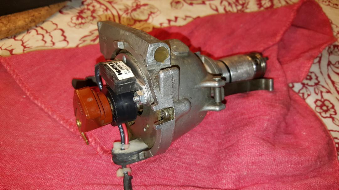 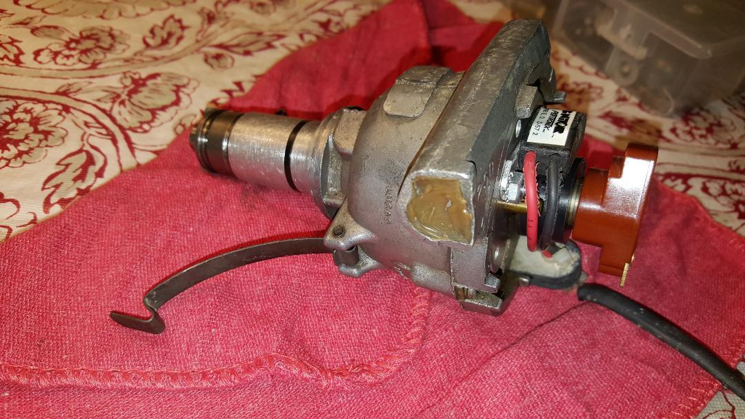 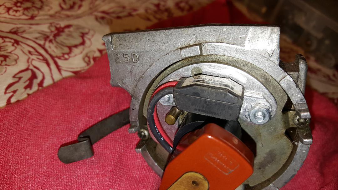 |
|||||||||
|
Tom Bradley Member
|
discogodfather wrote:Finally got around to pulling my distributor yesterday. Seems like it's a Lucas 25D that's had its vacuum advance converted to a Centrifical. The original distributor was a 25D that had centrifugal advance and vacuum retard (at least with the Stromberg carbs). This one looks like it had the vacuum retard removed by the PO, which is very common. If this is the original distributor, then it also had some extra stuff inside the shaft that kept oil from leaking out when it was mounted sideways in the 907 engine. As far as I know, nothing else out there has that. It looks to me to be in good shape, so I would say keep it. As long as it is not leaking oil or the advance is not working, it should not need rebuilding. Just replace the o-ring and lubricate the advance mechanism if it seems to need it. Then check that the total advance is 17 degrees going from 1000 to 2500 RPM. It has the Petronix ignitor. The ballast resistor and higher-ohm coil was to keep the original mechanical points from burning out. If you have a Pertronix 2 or 3 ignition, then you can go to as low as 0.6 ohm coil and get rid of the ballast resistor. If you have the Pertronix 1 version you probably need to keep the ballast resistor and a higher-resistance coil. Since I have the 2, I am not sure the exact numbers. If you check their web site, they should have specs for this. If you can afford it, I would switch to the 2 if it is a 1. Just fewer potential problems. One thing to keep in mind is that, if you have the original tachometer setup, going to a low resistance coil will probably make the tach read high. So be sure to use an automotive engine analyser with a tachometer function to do the tune-up. |
|||||||||
|
Esprit2 Member
|
At a glance, the obvious difference between the early 23D4 / 25D4 and the later 43D4 / 45D4 is that the head & cap diameters were smaller on the early models, and larger on the later ones. The 23D4 / 25D4 are too small to accept the later Ignitor II & Ignitor III. Well... I do know of one person who installed an Ignitor II into a 23D4, but he had to grind away at the amplifier's housing, reducing it's "Outside" radius until if fit into the 23 distributor head. However, doing that immediately voids any Pertronix warranty, so you go there on your own. The Pertronix in the photos is their first, basic Ignitor. It's a "points replacer", and little more. It is not a performance upgrade, and it cannot handle hotter coils. The basic Ignitor has no internal safeguards, and is both polarity and temperature sensitive. Know what you're doing before you install the Ignitor, and make no mistakes. It has "ZERO" tolerance for reverse polarity, and it will instantly and permanently fry if you get the polarity wrong on any one wire. You cannot undo a backward polarity connection fast enough to save it... instantly zap-dead, and it's permanently done. Use it with the car's OEM "breaker points" ignition coil and spark plug gap that would have been used with the breaker points. It requires more voltage to jump a larger spark plug gap. If you increase the plug gap for performance, then the high-tension side of the system will automatically run at a higher voltage. Increase the gap enough, and you'll need an aftermarket hotter coil to keep up with firing the plugs. For the basic Ignitor, keep the plug gaps at the car's original "breaker points" spark-plug gap... no greater. Either larger plug gaps or hotter coils, or both will cause the basic Ignitor to over-heat and fry. Using a coil that is hotter than the OEM "breaker points" coil will result in a higher current draw that will cause the basic Ignitor to over-heat and fry. Acrid smelling, smoldering, permanently fried, "Dead". It has no internal temp sensor to switch itself off when it gets hot, it just fries itself to a crisp and you buy a new one. The ignition system goes on & off as the engine runs. Picture the breaker points... open-closed-open-closed. They close to turn on and charge the coil. Then they open to disconnect the coil so the magnetic field colapses through the coil windings and fires the spark. So, in normal operation, the ignition runs at some Duty Cycle that's (??) closer to 50% than 100%. While the engine is running normally, with an OEM "points" coil, the Ignitor doesn't get hot enough to fry. However, if you turn on the ignition switch without starting the engine (oh, say, to debug a wiring problem), then it's a lottery... or roulette as to whether the ignition circuit will be On with a 100% duty cycle (points closed), or off (points open). IF the engine's position is such that the ignition is on (ie points closed/ amp 'on'), then normal 12 volt/ 'points' coil current running through the Pertronix full time will over-heat and fry the Ignitor's amp in about 10-15 minutes... depending upon the coil's internal resistance (Re). Far less time with a 'hot' coil. As above, once fried it's dead and not coming back. If you're going to work on your car with the ignition switch on, then either: 1) Disconnect the ignition coil, or... 2) Get your ducks all lined up, switch on only when ready, work fast, and switch off in less than 10 minutes, or... 3) Use a volt-ohm meter to determine if the ignition coil is 'ON' when the ignition switch is 'on'. If yes, then rotate the engine until the ignition switches off, and work with the engine in that position. If you're static timing the engine, then you may not have that option. The later, more expensive Ignitor II & III both have built-in safeguards against reverse polarity and thermal overload. You're protected from making a simple mistake and frying your brand new ignition system. The II & III can also handle high performance coils without melting down, and Pertronix claims they're happier with the hotter, "FlameThrower" coils. Regards, Tim Engel |
|||||||||
|
Esprit2 Member
|
It's not unusual for installing an electronic ignition system to cause a tach to stop functioning correctly. The needle may still move, but the indicated RPM may be way off. Pertronix sells a Tach Adapter Module. I've not used one, and can't say if it will work with a Smiths, Jaeger or JH tach. Regards, Tim Engel Last edited on 02-10-2020 11:34 pm by Esprit2 |
|||||||||
|
discogodfather Member
|
Esprit2 wrote:
I think I might have committed all of the list to things not to do with the ignitor including reverse the polarity, turn the ignition on for long periods of time (when I was doing some electrical diagnosis elsewhere) and then used a flamethrower coil. Then I wondered why the car was running so badly, misses, bad idle, popping, etc. Feels bad because I thought it was the carbs, two older Italian 45 DCOE's. I sold them and bought two new Spanish Webers. I miss the Italian ones! Oh well, live and learn. Should have read more about it to begin with. Going to go back to points for the time being with an original coil and the ballast resistor. Powerspark, the UK company I contacted, has a version of the 43D that is "high energy" that uses some electronic ignition module that can be used with a very low resistance coil. It's not bad at a little over $100 shipped to the USA. It seems to have the o-ring on the shaft. I know I have read a bit about how bad the Lucas copies are, but this seemed like an interesting option. |
|||||||||
|
Esprit2 Member
|
discogodfather wrote:Powerspark, the UK company I contacted, has a version of the 43D (Snip)... They all have an O-ring around the shaft housing... on the outside, where it slips into the oil pump housing. It's the Lotus-only internal lip-seal that is missing. It should be inside the housing. If you were to remove everything from inside the 'head' of the housing, you would see a small lip seal around the hole in the floor where the shaft would pass through. In all other Lucas distributors and clones, there would be no seal, just an open gap between the shaft OD and housing ID. That's a path for oil to flow from the engine into the distributor's head, and from there to leak out onto the side of the engine block. Regards, Tim Engel |
|||||||||
|
discogodfather Member
|
Esprit2 wrote: I received my $100 43D from Powerspark, I thought it would be interesting to check it out and compare with the stock unit. What I see taking them apart (also took my 25D apart) is that there isn't much difference on the shafts. The 25D Lucas unit has what appears to be a thin spiral cut channel on the side of it, and the cutout seems to be in a slightly different place. All the seals and bushings are similar. The centrifugal advance assemblies are a lot different. Could it be this 25D I have is not a special Lotus unit? I don't think I had any oil leaks, at least the inside of the distributor is clean, nothing in the cap. Maybe I am looking in the wrong place? The PowerSpark unit has a pretty robust looking electronic switch unit, it looks like a beast- this is the one they claim has the capability of a low resistance coil (like .7 ohms) and 3x the spark. The old Lucas 25D I have has a 41584 A number followed by a 48 and 74. 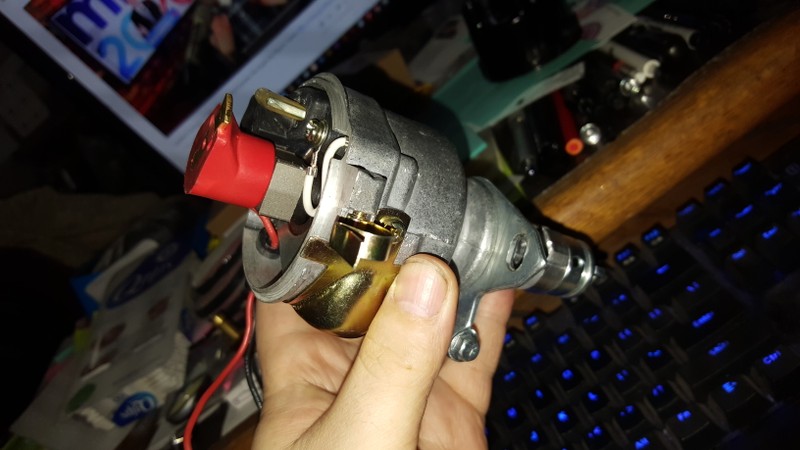 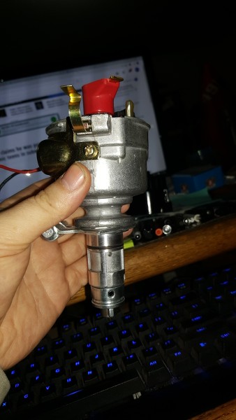 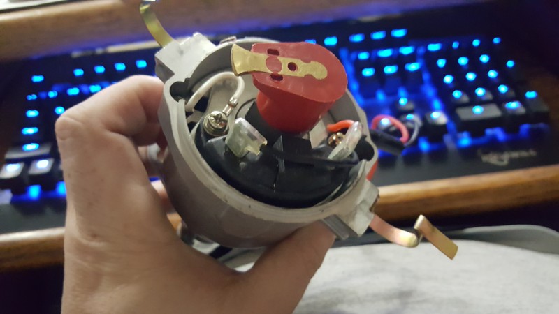 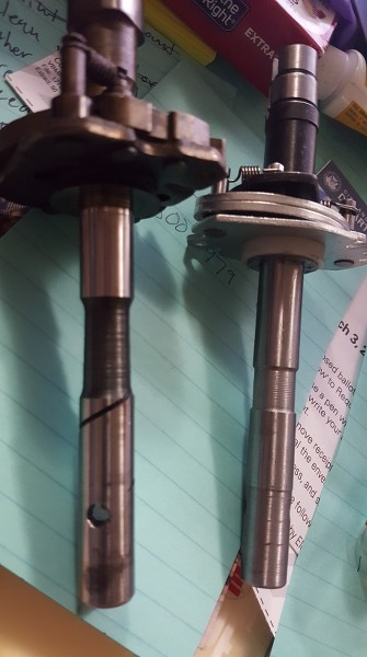 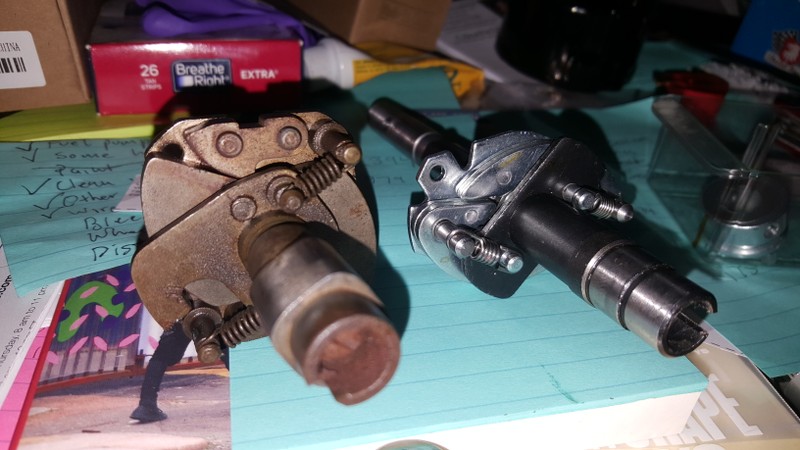 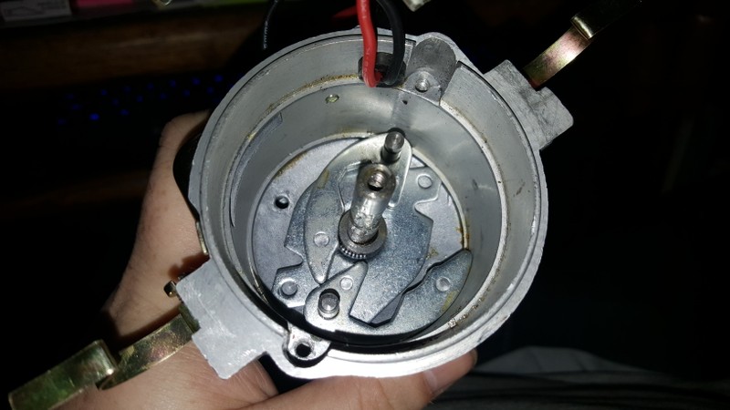 Last edited on 02-12-2020 05:46 am by discogodfather |
|||||||||
|
discogodfather Member
|
Just picked up on this difference after re-reading Tim's explanation- there is a black metal ring on the bottom of the floor of the distributor housing. It's not much of a seal though, it looks to be worn well in.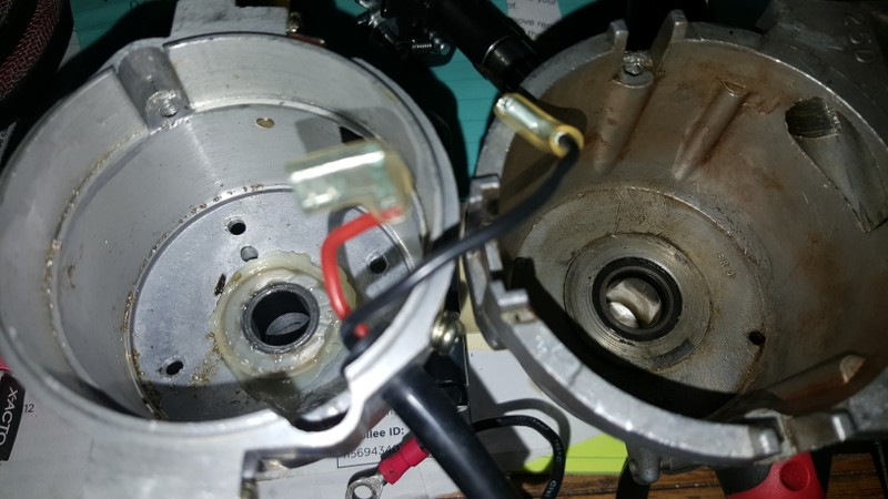 |
|||||||||
|
Tom Bradley Member
|
discogodfather wrote:What I see taking them apart (also took my 25D apart) is that there isn't much difference on the shafts. The 25D Lucas unit has what appears to be a thin spiral cut channel on the side of it, and the cutout seems to be in a slightly different place. All the seals and bushings are similar. The centrifugal advance assemblies are a lot different. I also pulled one of my distributors apart and it looks the same as yours. I think the spiral acts as a pump to push the oil back towards the engine. As long as you are not getting any oil inside the distributor it should be OK. The centrifugal advance on the JH was made specific for the Lotus engine. It is unlikely that a general purpose distributor like Powerspark will be the same. If you use it, your car will probably run OK, but may not have the performance or smooth acceleration that you will get with the original. Personally I think that going back to mechanical points is a bad idea. These are much more prone to problems than even a basic solid state switch. The electronic switches in the Ignitor 1 are unlikely to be bad if the car was running at all. When these go bad, they usually die completely, not get unreliable. If the car was running poorly it was more likely caused by other things like a bad distributor cap or poor electrical connections somewhere. BTW, Pertronix does make an Ignitor 2 specifically for the 25D4 distributor. That is what I have on mine and has been working well for several years now. It is available from Amazon: https://www.amazon.com/Pertronix-9LU-142A-Ignitor-Lucas-Cylinder/dp/B00AWQRJRO |
|||||||||
|
discogodfather Member
|
Tom Bradley wrote:
Interesting, I thought the exact same thing in terms of that spiral cut- some way to push oil in the opposite direction. The dizzy is marked with a "74" on there and I first thought it might be one of the earlier units without a shaft seal, but I have no idea. I did manage to find a source for the actual seals used in the proper "lotus" version from a source in the UK. Looks like a simple lip seal. This is for the 43/45: https://www.sjsportscars.com/parts-and-accessories/SJ754.htm |
|||||||||
|
Tom Bradley Member
|
Replacements for the internal distributor seal has come up numerous times on this forum. Here is the link to one of them: http://www.jensenhealey.com/forums/view_topic.php?id=2134&forum_id=5 (look at post #2) I used the recommended one from Mcmaster Carr a couple of years ago and have had no problems so far. I had to press the steel bearing down a bit to install it in the opening but did not have any problems with that. Getting the distributor apart to see how the shaft was designed was much harder. |
|||||||||
|
Esprit2 Member
|
discogodfather wrote:Just picked up on this difference after re-reading Tim's explanation- there is a black metal ring on the bottom of the floor of the distributor housing. It's not much of a seal though, it looks to be worn well in.All Lucas distributors have a rubber O-ring around the outside of the long, slender shaft housing, where it slips into the engine. ONLY the Lotus/ J-H distributors have an internal rubber lip seal. The standard Lucas distributor has steel bushings for the shaft, one at each end of the long shaft housing. The top one is pushed in flush with the surrounding floor of the upper 'head' part of the housing. If a seal is present, then the upper bushing was simply pushed about 4-5 mm deeper into the housing to make room for the rubber seal. Then the seal was pushed in until flush with the surrounding floor... or a wee bit below flush. If you see a rubber seal, then the distributor is configured for a Lotus/ J-H engine. If you see the edge of a steel bushing, then it's not. The spiral on the shaft is there to act as a 'pump' to keep oil from migrating toward the head of the distributor. It's effective when the distributor is mounted vertically, or nearly so. However, it's NOT effective when the distributor is mounted horizontally, and oil will leak out via the head of the distributor. So Lucas added the rubber lip seal specifically for Lotus/ J-h applications... no others. In North America, Delta Motorsports, JAE, and Dave Bean Engineering all stock the seal for Lucas' Lotus/ J-H distributors. The same seal also fits the Pertronix and 123 distributors that are close clones of Lucas. Source: GACO IND49248 (Lucas OEM Seal). Source: Chicago Rawhide CR4912 (exact replacement). Source: Transcom TCM 13x19x3VG (nearest metric size). Source: McMaster-Carr 9505K17 (different seal style... but works). In the GACO IND49248 part number, IN = INternal, and D = Distributor. It's made for the purpose. GACO Seals Website: https://gacoseals.co.uk/ GACO Seals Directory: https://gacoseals.co.uk/gaco-special-oil-seals-directory.html GACO = George Angus & COmpany (Oil Seals). Regards, Tim Engel Last edited on 02-13-2020 06:29 pm by Esprit2 |
|||||||||
|
discogodfather Member
|
Thanks Tim and Tom, ordered some seals and am going to install them. I also will attempt to install one on the newer 43D copy, even though it needs some machining in the lather. Thanks, Chris |
|||||||||
|
Esprit2 Member
|
Chris, Are you sure that machining is required? I'm not familiar with which 43D copy you have, but in all the Lucas and Pertronix/ 123 clones I've seen, the shaft bore is straight, no steps. Installing a seal only requires that the top bushing be pushed 4-5 mm deeper into the bore to make room for a seal. Regards, Tim Engel |
|||||||||
|
discogodfather Member
|
Esprit2 wrote:Chris, The new 43D I have has much smaller bushing sizes and a thicker aluminum shaft. The seal seems to need slight over .75" diameter hole to sit in, so I can push the bearing in and then cut a .75" seat for it. On the right you see the Lucas- the "steel ring" that was sitting at the top turned out to be a nearly petrified rubber seal- it was so hard I mistook it as steel. Removed it with ease, waiting on my new seals to come in. Great advice Tim! At the rate I am going I will have two viable distributors to test. 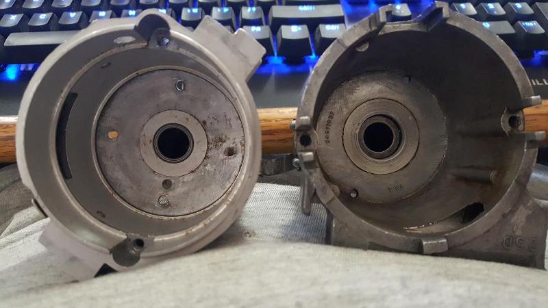 |
|||||||||
|
discogodfather Member
|
Was able to cut a nice 4mm deep by around 17.5mm diameter recess for the seal in in the new 43D housing using a small lathe and a boring bar. Came out nice! I might consider doing this to a Flamethrower or 123 in the future, but for now I am concentrating on a stock unit rebuilt and comparing it to the new 43D. I know the advance curves will be totally different. The old Lucas 25D has a 11 degrees stamped on the advance arm. That seemed a bit odd, been reading 13 is stock? 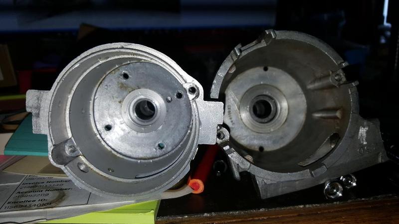 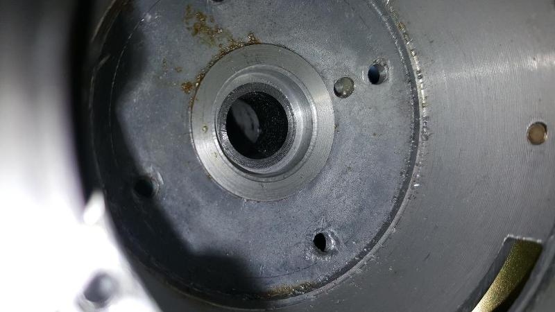 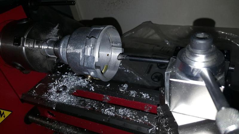 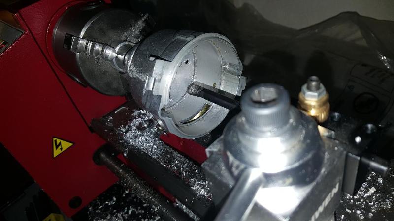 |
|||||||||
|
Tom Bradley Member
|
Wow, you have some nice equipment available and know how to use it. I am envious. Here is the distributor advance spec from the JH shop manual. I did not notice before, but the advance for the 45D distributor is significantly different from the 25D. Mine is also stamped with 11 degrees, but when I check the advance with a timing light I get the spec'd 17 degrees from 1000 to 2500 RPM. Attachment: JH5 Distributor advance.jpg (Downloaded 140 times) |
|||||||||
|
Esprit2 Member
|
Well, I'll have to defer to what you see in your hands, but the original 43/45 Lucas distributors used the same seals as the earlier 23/25 distributors, and the Pertronix/ 123 clones mimic the 43/45. With them, all that was required was to push the top steel bushing 4-5 mm deeper into the straight bore in order to make room for the seal. I'm impressed by your photos of all your machine work, I'm just surprised that it's necessary. *~*~*~* A friend and I recently rebuilt the 45DM4 out of this 1984 Turbo Esprit's 910, the stock GACO seal was present, and it's the same as the one in his 1977 S1 Esprit's 25D4. So now I'm quite curious about your need to machine the bore. Regards, Tim Engel Last edited on 05-16-2020 11:29 pm by Esprit2 |
|||||||||
|
redracer Member
|
The very early J-H distributors did NOT have an internal oil seal in(later ones did); for those like that I had worked on, I knocked the upper steel bushing down (as Tim has said) and installed a slightly thicker-than-original "rubber"(neoprene) seal; part # 4702 for both CR & SKF. The dimensions are: 12mmX19mmX5mm(original was 3 mm; someone has previously written 1/2" inner diameter, but that is TOO LARGE). I use Permatex #2 on the outer shaft housing for extra peace-of-mind! btw; if you ever refer your dizzy to a "rebuild" house, the 5 digit # on the outside of the dizzy is incorrect in that these numbers refer to a dizzy spinning in a CCW direction, whereas ours spin CW. You may have noticed the arrow in the top of the dizzy has been filed off just for that reason! hope this helps, bruce |
|||||||||
|
discogodfather Member
|
Esprit2 wrote:Disco, Was again experiencing tuning problems at high RPM and decided to take the head off, it actually came out way easier than I thought. I phoned and talked to Barry today and he's a great guy. I really think he might have built this engine 20 years ago, he could not remember but it's pretty sure upon looking into it for the first time. The heads were ported, the work is immaculate, and it has the high comp J&E machined pistons. Liners look great and all it took was a rag and a wipe down and they look new. I can still see some of the crosshatch on the liners. Again the mystery cams bothered me because I could not find any marks. Barry said to look behind the thrust plate and sure enough, there was "104" imprinted on both. So now the mystery is over, I can time them! I was about to send them off for a set of new 104's so this phone call saved me $300. I'll also be able to tell how badly my timing was off for the last 2-3k miles, so that will be enlightening. Thanks for the recommendation Tim! When I bull these valves and inspect the seats and there is any damage at all I will be sending them over to Barry for some work. |
|||||||||
|
Esprit2 Member
|
Disco, I'm not so sure about the cam being a Lotus 104. A 'Lotus' 104 cam had 44444444... stamped all around the exposed bit of shank between the front of the cam carrier and the back of the pulley. Many cam grinders produced '104' cams that did not match the Lotus 104 specs, and "104" as a name was used about like "3/4 Race" was used for American V8 cams. L-o-n-g ago, I bought a pair of "104" cams on eBay, and they are NOT Lotus 104 cams. They have a much hotter profile, and they're just sitting on a shelf because I don't know what they are or how to time them. Like yours, they were stamped with "104" on the back end. So, I called Delta Motorsports, described the markings, and they said it wasn't their 104 cam. So I called Delta Cams, and they said it wasn't theirs. I never did find out whose '104' cams they were, but the lobe profile does not match the genuine Lotus 104 cams I already had on hand. Lotus 104 Cam Specs: 0.415" Lift (0.410/ 0.415"/ 0.420", depending upon who you ask). 32° .Int Opens, BTDC 60° .Int Closes ABDC 60° .Exh Opens, BBDC 32° .Exh Closes ATDC 64° .Overlap, Degrees 272° Duration, Degrees 104° MOP, Degrees On Delta Motorsports website, they list their "104" cam as Part No BLL-104, 280° Duration, 0.420" lift. Good luck, Tim Engel |
|||||||||
|
Esprit2 Member
|
Sorry about the redundancy. It seems I posted something similar back in February. Tim |
|||||||||
|
discogodfather Member
|
Esprit2 wrote:
Ah, the mystery deepens, I'll send them with the head to Barry to try and make some sense out of it. Profiles are very sharp indeed. Intake seems to be marked DB3-104? Could that be Dave Bean? 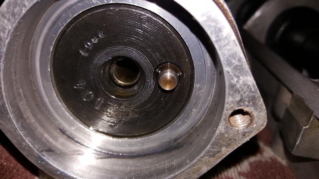 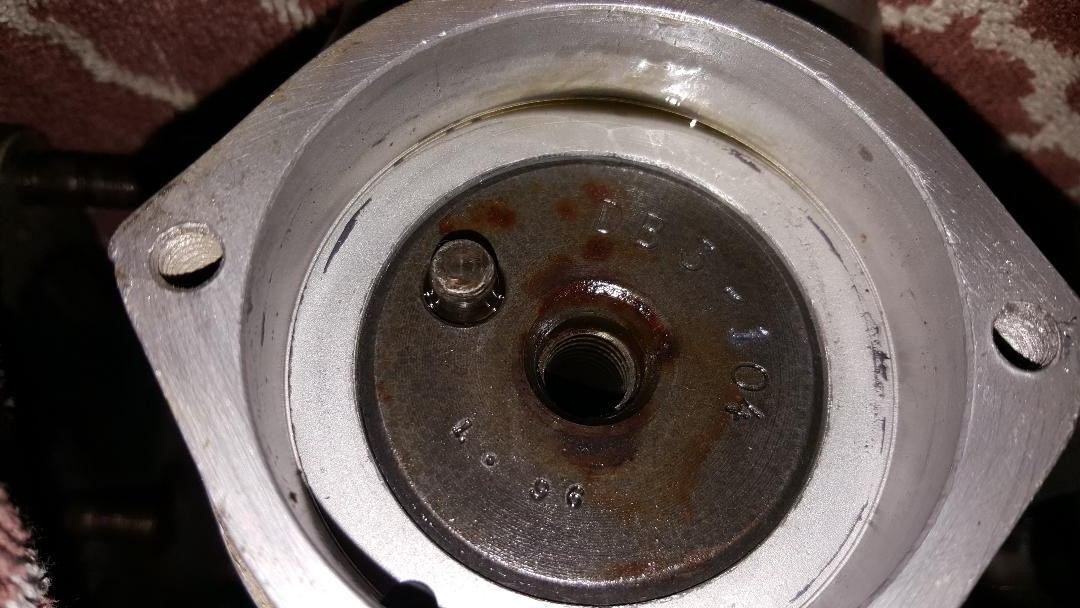 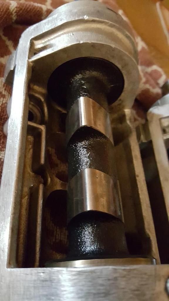 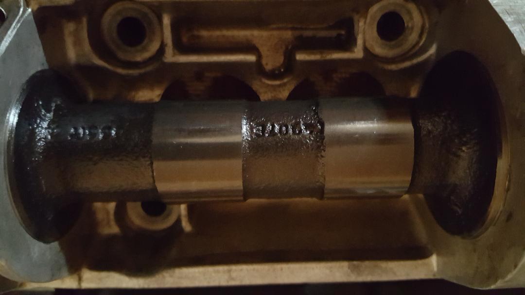 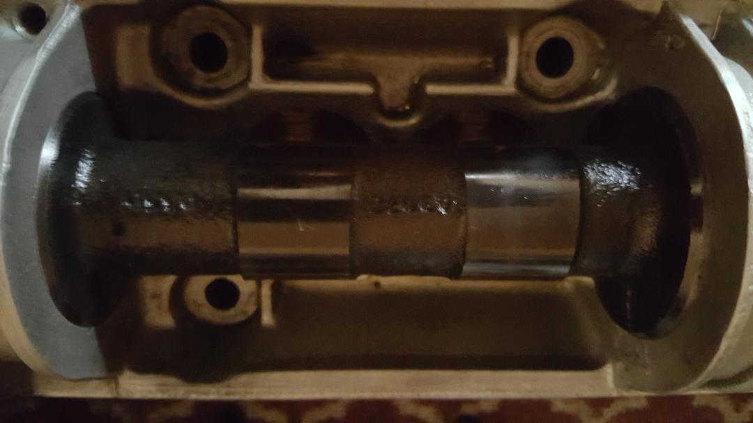 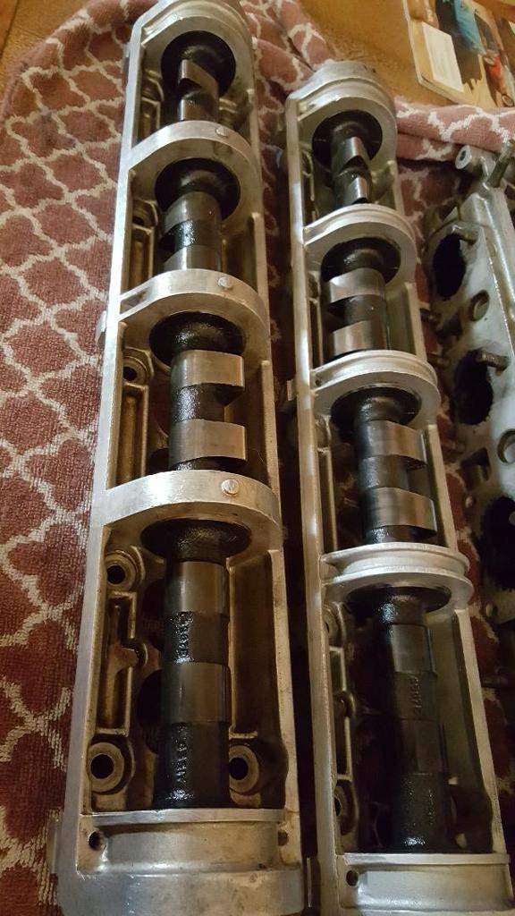 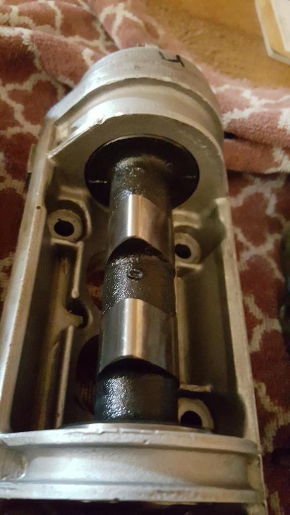 |
|||||||||
|
redracer Member
|
Very interesting; you have a '73 cam housing on the right(the bearing sizes were 0.001" smaller than the later housings.) There used to be galling on those earlier housings which was really caused by lack of oil(leaking from the cam covers) rather than too tight a clearance. |
|||||||||
|
discogodfather Member
|
redracer wrote:Very interesting; you have a '73 cam housing on the right(the bearing sizes were 0.001" smaller than the later housings.) I was wondering about that difference, assumed it was supposed to be like that. I'll see if I can pick up a newer one for the rebuild. Are they the same otherwise in terms of intake and exhaust? |
|||||||||
|
redracer Member
|
Yes, they're the same. Again, the earlier cam housings were 0.001" smaller on each of the 5 cam housing "bearing" surfaces. |
|||||||||
|
discogodfather Member
|
redracer wrote:Yes, they're the same. Again, the earlier cam housings were 0.001" smaller on each of the 5 cam housing "bearing" surfaces. Just to be safe, because I typically get everything backwards, the housing with the cutouts on the central hoops is the earlier version with the smaller bearing surfaces and the one with the filled in and a kind of nipple sticking up is the later style with the looser tolerances? |
|||||||||
|
redracer Member
|
correct; ypur last photo is the earlier housing. It has the "ribs" slightly hollowed/grooved out, whereas the later ones have the little nib sticking up in the middle of the ribs. |
|||||||||
|
Esprit2 Member
|
discogodfather wrote:Intake seems to be marked DB3-104? Could that be Dave Bean?I've never seen the DB3-104 designation before... which means nothing. The only Dave Bean cam designation of which I'm aware is BLL-104. That's the same designation that Delta Motorsports uses. BLL - "Bean Lotus Leeslay", and I have no idea what or who Leeslay is. Regards, Tim Engel Last edited on 05-16-2020 11:52 pm by Esprit2 |
|||||||||
|
Esprit2 Member
|
discogodfather wrote:Intake seems to be marked DB3-104? Could that be Dave Bean?Disco, Have you called Dave Bean Engineering to ask if DB3-104 is theirs? Even if BLL-104 is current, DB3-104 'might' be something they offered before. Regards, Tim Engel Last edited on 05-16-2020 03:57 am by Esprit2 |
|||||||||
|
discogodfather Member
|
I called Barry Spencer and he gave me really good info. He thought it was a Dave Bean cam so I called them. Turns out it is a Dave Bean cam, it was one of Dave's propriety grinds called 104 but hotter. They still sell it. It has a .420 lift and 290 duration, 104 lobe centers. The cam is in pretty good shape so I was going to use it again, also considering the cost of one of these cams from them is $400. With these numbers cam timing must be even more critical. Amazing these valves aren't bent, but I still have to pull a few and test them. Right now the plan is to disassemble, clean, and check everything. If it's ok then a lap and back together and degree it in properly. I'll be using the ARP studs, was thinking of upgrading to some Gary Kemp parts, he has a heavy duty spring kit with titanium retainers, chrome moly tappets, solid machined spring bases. Very expensive but tempting. If things get too hairy it's off to Barry for him to work on. If the seats are shot or any of the valves too bad I was also thinking about going with the sunbeam tiger big intake valves, is that a good upgrade? Was planning to keep things 2.0 for now. |
|||||||||
|
discogodfather Member
|
One thing that's again bothering me is the info about opening and closing. Ken at Dave Bean didn't seem to have this information, all he could give me was .420 lift/ 290 duration / 104 Lobe Centers. I asked if this meant that the cam could be timed to the Lotus specs for the 104 cam, which Tim generously provided earlier: LOTUS Cam ID. . . . . 104 Int. Opens, BTDC . . 32° Int. Closes, ABDC . . 60° Exh Opens BBDC. . . 60° Exh Closes ATDC. . . 32° Overlap . . . . . . 64° Duration. . . . . . 272° MOP. . . . . . . . . 104° Found it kind of odd they don't have the information, they did send me this procedure. Am I missing something here, or do I need more into on the cam grind? |
|||||||||
|
Esprit2 Member
|
discogodfather wrote:Ken at Dave Bean didn't seem to have this information, all he could give me was .420 lift/ 290 duration / 104 Lobe Centers.Did Ken give you a direct answer to your question? If not, the answer is, "Yes". Speaking "American-English", in a single-cam Detroit push-rod V8, "Lobe Centers" is the same thing as speaking Brit-English and saying "MOP" (Maximum Opening Point). So timing the DB3-104 cam to 104 "Lobe Centers" is the same as timing the Lotus 107 or 104 cams to 104 "MOP". Use the Lotus Green-dot, 104 MOP pulleys. Regards, Tim Engel Last edited on 04-18-2020 01:31 am by Esprit2 |
|||||||||
|
Esprit2 Member
|
"LOTUS" Cam ID . . . C. . . . . . . D . . . . . . . E. . . . . . "104" .. . . .105. . . . . 106 . . . . "107" . . . . 108 Int. Opens, BTDC . . 26° . . . . . 25° . . . . . 27.5° . . . . 32° . . . . . ??° . . . . . ??° . . . . . 22° . . . . . ??° Int. Closes, ABDC . . 66° . . . . . 65° . . . . . 52.5° . . . . 60° . . . . . ??° . . . . . ??° . . . . . 50° . . . . . ??° Exh Opens BBDC. . . 66° . . . . . 65° . . . . . 52.5° . . . . 60° . . . . . ??° . . . . . ??° . . . . . 50° . . . . . ??° Exh Closes ATDC. . . 26° . . . . . 25° . . . . . 27.5° . . . . 32° . . . . . ??° . . . . . ??° . . . . . 22° . . . . . ??° Overlap . . . . . . . . . 52° . . . . . 50° . . . . . 55°. . . . . . 64° . . . . . ??° . . . . . ??° . . . . . 44° . . . . . ??° Duration. . . . . . . . . 272° . . . . 270° . . . . 260°. . . . . 272°. . . . . 296° . . . . 320°. . . . 252° . . . . 304° MOP. . . . . . . . . . . . 110° . . . . 110° . . . . 102.5° . . . 104°. . . Per Event . Per Event. . . 104° . . Per Event Lift. . . . . . . . . . . . . 0.340". . . 0.350" . . . 0.344" . . . 0.420" . . . 0.433" . . . 0.450". . . 0.378" . . . 460" The A & B cams were development cams, and I've never seen specs published for them. The 105, 106 & 108 were competition cams that Lotus never sold to the general public. I only mention them to fill out the 'naming' number series. Then Dave Bean sells a BLL-104, BLL-105 & BLL 107 that apparently do NOT mimic the original Lotus 104, 105 & 107. And to add further confusion, It appears that Dave Bean also sold/ sells (?), a DB3-104. Is that a BLL-104 with a different name, or is it yet again different. And are there other CB3 cams? DBE. . . . . . . BLL. . . . . DB3 . . . . BLL. . . . . BLL Cams . . . . . 104. . . . . 104 . . . . 105. . . . . 107 Duration . . . 290° . . . . 290° . . . 295° . . . . 270° Lift . . . . . . . 0.420". . . 0.420" . . 0.425". . . 0.375" Delta Motorsports sells the same BLL series of cams that they seem to be getting from Dave Bean Engineering. Unfortunately, they've not been able to get any more information out of DBE than you or I. In either case, if you have heard about the Lotus 107 cam improving the 907's low-end torque and driveability, the BLL-107 cam is NOT the same. Durations of 252° for the Lotus cam, and 270° for the BLL cam can NOT give the same result. Similarly, if you're thinking about a Lotus 104 cam with 272° duration for a street-hot cam, the BLL-104 with 290° duration is NOT the same. I mentioned earlier that I bought a pair of "104" cams on eBay, and they turned out to be "Delta 104" cams. What's that? Delta Motorsports knows nothing about them, and Delta Cams disavows any knowledge of them. But they are not the same as Lotus 104 cams, and I don't know what they are. If you go out into the market place shopping for a 104 or 107 cam, what is it that you really have in mind? In the early days, when J-H owners started swapping cams to improve low-end torque and driveability, the Lotus 107 was all there was and they liked it. It was only after other vendors wanted some of the action that other 107's began to show up. Same with Lotus 104 cams being first, and others coming along later to muddy the waters. Established names provoke certain expectations. I do wish that aftermarket companies would either accurately clone the originals (may be intellectual property issues involved), or be creative enough to come up with their own names for different products. Personally, if a cam doesn't say Lotus on it, I don't know what it is. Regards, Tim Engel Last edited on 05-16-2020 11:07 pm by Esprit2 |
|||||||||
|
discogodfather Member
|
It frustrates me. Without the specs who knows whats really going on. Dema Elgin taught me years ago that the way people bought aftermarket cams was to rip the sheet out of the catalog, pin it to the wall, and then throw a dart at it and pick the cam it landed on. He also taught me to measure and plot a cam, which my dumb mind forgot years ago. I should have payed more attention. Who does sell an actual 104 cam? I see Greg Fletcher has it advertised as a genuine Lotus grind. I'm tempted to go this route just so I know whats going on and eliminate some of the "secret sauce" variables. Ken seemed to indicate that Dave was especially secretive about their proprietary grinds. |
|||||||||
|
Esprit2 Member
|
Here's a basic sketch of the 'Lotus' 104 cam lobe. Attachment: Cam - 104 Lobe drawing.jpg (Downloaded 132 times) |
|||||||||
|
Esprit2 Member
|
And a similar one for the 'Lotus' 107 cam lobe. Attachment: Cam - 107 Lobe drawing.jpg (Downloaded 132 times) |
|||||||||
|
discogodfather Member
|
So, ready to bolt on the heads, just waiting for a couple extra shims to get me to .007" and .012" on intake and exhaust. So much easier to do this when the head is off! So my veiner pulleys had no real objective marks other than the little bits of paint I had used to line everything up in the past. Now I am ready to bolt it all together and degree the cam, got a very nice setup on load from a friend. Problem: if you don't even have the initial idea of where the cams should go (this would not be the case if I had the green dot pulley to use with the 104), then how to you bolt it up. My solution: I put the cam towers in place and have everything shimmed correctly, then measured the intake and exhaust valve opening and closing points, roughly. The RED dots on the pulley I marked are those events. I then looked at the cam info for the 104 from Tim, and it says: Intake Opens 32 Degrees BTDC Exhaust Closes 32 Degrees ATDC So, the cam rotates at 1/2 the crank speed in a 4 stroke, regardless. I took 32 degrees, devided by two to get the cam degrees (it's my understanding all cam data is always in crank degrees) and then used a protractor to measure and rotate the cams into the correct position they should be AT TOP DEAD CENTER. Those are the WHITE marks. So now I have a very rough objective point to start with when bolting the cams in place, the next step is to actual degree it in on the engine. Question: Is there any data for the 104 cams at .050" or some kind of lift? It's hilarious that Dave Bean sent me a big write up on how to degree in cams that completely emphasizes the importance of degreeing at lifts and how it's much more accurate and better, but then no information about timing their cam!? I looked all over the Internets and no one seems to have data at any lift. I guess I will just have to use the data at zero lift.  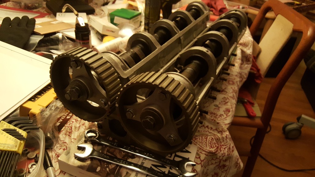 |
|||||||||
|
Esprit2 Member
|
discogodfather wrote:So, ready to bolt on the heads, just waiting for a couple extra shims to get me to .007" and .012" on intake and exhaust. So much easier to do this when the head is off!Disco, are you shooting for 0.007" & 0.012" dry during trial assembly? What sealant will you be using between the cam carrier and head. If it's an anaerobic sealant, like Loctite 518, then it's film thickness is 0.0005" (half a thousandth). In that case, dry-shim short by that half a thousandth to 0.0065" & 0.0115". Then the film thickness will 'float' that dry setting up to 0.007" & 0.012" during final assembly with the sealant applied. discogodfather wrote: (Snip)... I took 32 degrees, divided by two to get the cam degrees (it's my understanding all cam data is always in crank degrees) and then used a protractor to measure and rotate the cams into the correct position they should be AT TOP DEAD CENTER. Those are the WHITE marks.Here's a way to double check your work. If you had stock pulleys installed with the timing marks aligned ON the centerline between the cams, and... If you removed the nut & washer so you could see the ends of the camshafts in the pulley bores, then... You would see that the keyways are located above that centerline between the cams. The intake keyway is in the upper-left quadrant, at about 10:00 o'clock The exhaust keyway is in the upper-right quadrant, and about 2:00 o'clock. Each cam MOP has it's keyway a certain angular distance (degrees) above that centerline between the cams. _97° MOP = 21.25° . . . . 97° is the Blue timing dot on a SINGLE-MOP pulley. 100° MOP = 19.75° . . . 100° is the Blue timing dot on a DUAL-MOP, Red-dot / Blue-dot pulley. 104° MOP = 17.75° 105° MOP = 17.25° 110° MOP = 14.75° 115° MOP = 12.25° above the centerline between the cams The trick (and the Achilles Heel) will be in accurately locating the radial centerline of the keyway, and the centerline between the two cams, and accurately measuring the angle between them. discogodfather wrote: Question: Is there any data for the 104 cams at .050" or some kind of lift? It's hilarious that Dave Bean sent me a big write up on how to degree in cams that completely emphasizes the importance of degreeing at lifts and how it's much more accurate and better, but then no information about timing their cam!?First, not all 104 & 107 cams are created equal. Unfortunately. Lotus designed the originals, and named them. Then, every Tom, Dick & Harry aftermarket cam grinder on the planet came out with their own 104 & 107 cams with different timing specs. That has created great confusion... why couldn't they have exercise a small shred of naming creativity for their own cams. You're using Dave Bean BLL-104 cams, which are slightly different and call for 105 MOPs, so you should use Dave Bean's instructions... not Lotus' instructions. Unfortunately, Dave Bean himself passed away a couple of years ago, and he was 'the' tech guy, 'the' engineer at DBE. And he didn't share much of the details about things he developed... including cams. The sales staff do not know the answers to your questions. I recently asked Ken Gray at DBE to contact their cam grinder, talk with an engineer, and get all the info about each of the cams they're getting from that company. He said he would. That doesn't help you for now. I have old Dave Bean BLL specs from the mid-1990s... I can guarantee the BLL design hasn't been changed since then, but... Lotus 104 = 32° / 60° / 60° / 32° -- 272° Duration -- 64° Overlap -- 104° MOP BLL - 104 = 31° / 61° / 61° / 31° -- 272° Duration -- 62° Overlap -- 105° MOP Lotus 107 = 22° / 50° / 50° / 22° -- 252° Duration -- 44° Overlap -- 104° MOP BLL - 107 = 24° / 54° / 54° / 24° -- 258° Duration -- 48° Overlap -- 105° MOP Lotus never quoted duration at any specific lift value, such as 0.050". Nor did they say duration was seat-to-seat, or not. Nor quote an angular position off of TDC at which 0.050" lift occured... either opening or closing. So, no direct answer to your question. However, I knew an engineer at Lotus (retired), and he gave me the information on the two cam illustrations I posted above. He further stated that Lotus quoted duration between the tops of the opening and closing ramps. You won't find that in print from Lotus, but the info on the illustrations I posted is all per that engineer. If you look at the two cam illustrations, keeping in mind that Lotus quotes cam duration between the tops of the opening and closing ramps, look at the ramp dimensions and you'll see that the 104 cam's opening & closing ramps are 0.010" high, and the 107s are 0.012" high. That's as close as you're going to get to a "measuring height" from Lotus, but it's not 0.050"... ADAPT. In the 104 illust'n, the profile contour is 68° before, and 68° after MOP (ie, straight up centerline), or 136° total expressed in 'cam' degrees. But timing is expressed in crankshaft degrees, so 136° x 2 = 272°... which is the duration that Lotus quotes for the 104 cam. If you start with your dial indicator zeroed on the base circle, rotate the cam until the dial indicator 'just' reads 0.012". Note the angular position on the degree wheel... you should have rotated 20° to that point. Rotate the cam, up over the hump and back down, until the dial indicator once again 'just' reads 0.012", and note the position on the degree wheel. You should now be at the top of the closing ramp. The difference between the two degree wheel readings (from 0.012" before to 0.012" after) should equal 272° for a 104 cam... +/- manufacturing tolerances. One half the difference between the two degree wheel readings is the half way point of your rotation, which is also be the lobe's Maximum Opening Point (MOP). Regards, Tim Engel Last edited on 05-16-2020 07:47 am by Esprit2 |
|||||||||
|
Esprit2 Member
|
discogodfather wrote:It's hilarious that Dave Bean sent me a big write up on how to degree in cams that completely emphasizes the importance of degreeing at lifts and how it's much more accurate and better, but then no information about timing their cam!?Disco, Would you please forward a copy of Dave Bean's write-up as a file attachment to a PM. I'll read through it and see if it makes sense. Regards, Tim Engel |
|||||||||
|
discogodfather Member
|
Esprit2 wrote: The keyway for these cams is cut right on the intake/exhaust lobe centers. The wheels are the Dave Bean veniers (square tooth) and they have some arbitrary 2 degree timing marks that line up with the intake and exhaust opening/closing events. The keyway for the intake faces at about 9/10 o'clock when at TDC, the exhaust at about 3-4 o'clock. The intake lobe and the exhaust lobe positions, as I marked them, have both the intake slightly open (just opened) and the exhaust slightly open (about to close). Does that make sense? If I clock the intake at 10 o'clock (upper left hand quadrant) they will be about 100 degrees from opening, and the exhaust at 2 o'clock (upper right hand quadrant) would be about 100 degrees after closing. Last edited on 05-16-2020 07:37 am by discogodfather |
|||||||||
|
discogodfather Member
|
I think I just answered my own question- cam timing is always TDC on the compression stroke. I think I measured it up for TDC on the intake stroke. Both valves need to be closed, correct? So that would explain why I am 180 degrees from what Tim suggested: intake at 10 o'clock and exhaust at 2 o'clock, just for an initial setting to bolt down the cam towers and get everything ready. |
|||||||||
|
Esprit2 Member
|
discogodfather wrote:I think I just answered my own question- cam timing is always TDC on the compression stroke. I think I measured it up for TDC on the intake stroke. Both valves need to be closed, correct? So that would explain why I am 180 degrees from what Tim suggested: intake at 10 o'clock and exhaust at 2 o'clock, just for an initial setting to bolt down the cam towers and get everything ready.Cam Timing is always spec'd, and timed with the #1 cylinder at TDC. That's your starting point. The cam lobes need to be where they need to be... they stay put. Then the adjustable pulleys allow you to then rotate the outer rim & teeth as need be to mate up with the timing belt. The timing belt is in a fixed position by the crankshaft, which by definition is not allowed to rotate off of the TDC position during timing... so the belt can't move either. The pulley rim must go to the belt, without disturbing the cam lobe positions. Anything that affects the distance between the crankshaft centerline and the camshaft centerline affects the amount of slack in the un-tensioned belt loop (tensioner backed all the way off). The crank must stay at TDC (it can't be allowed to move), so the slack in the belt strand between the crank and the exhaust cam pulley must go up and over the pulleys to/ or from the tensioner... rotating the pulleys a little. If the head and/or cam carriers have ever been milled to flatten a warp, if the block has ever been decked, or just a simple stack-up of production tolerances... anything that alters the "PERFECT" center-to-center distance also alters the amount of slack, and hence, the positions of the cam pulleys at TDC, and the alignment (or lack there of) of the timing dots. So, the cam lobes need to be where they need to be when at TDC, and the adjustable pulleys only allow the rim to be moved as necessary to follow the belt that might be moving as non-standard slack is pulled out of the timing belt. Make sense. I previously gave you angular locations for the cam/ pulley keyway locations above the centerline between the two cams. That is where they (and the lobes) need to be when the crank is at TDC. Now you're just screwing around with the pulley rim. NOTE: Head gasket thickness has a large affect upon the slack in the timing belt loop. Therefore, degreeing the cams is done 'after' the engine is fully assembled and the head is torqued down (gasket it crushed to final dimension). Only then can you accurately 'degree' the cams. You are trying to pre-set the adjustable pulleys to a ball park setting (close, but not spot on) with the head off the engine. Don't confuse that with actually 'degreeing' the timing as a final procedure. See the attached JPEG. JHPS only allows a 100kb maximum file size, so that's all the resolution I can give you here. The intake cam lobe is shown in three positiions. The one pointing down & right is MOP... the intake valve is at it's Maximum Opening Position. The lobe to the upper left is where it would be when the #1 cylinder is at TDC. There's a note in bold red font, "To Red Centerline, 14.75° degrees... that's for a 110° MOP. In the lower right corner of the page, there's a chart of angular dimensions for other MOPs, and 105° MOP is 17.25° degrees above the centerline. You can either: 1) McGyver a way to establish a 'working' centerline between the two cams, and a protractor or cut pie wedge to indicate 17.25° above the centerline, or... 2) Put a degree wheel on the cam, and a dial indicator perpendicular to the tappet (NOT on the lobe itself). Rotate the cam to find the Maximum Opening Point via the dial indicator, and zero the degree wheel. Now use the attached drawing to map your way (rotating the cam) to the 17.25° dimension above the centerline between the cams. The details for the exhaust cam lobe are just the mirror image of the intake lobe, so they're not included on the drawing.... just a red centerline for where the keyway should end up. In either case above, the result will be a rough, ball-park approximation of where the cam should be... ignoring all the factors that can affect the amount of slack in the timing belt prior to tensioning. Now, with the keyway's located, you can move the pulley's rim to align the timing dot with the centerline between the cams. But be aware that timing with the head on a bench is not allowing for head gasket crushed thickness, or for any past milling of parts. Install the head on the engine, and the end result of this work will be wrong to some small degree. But not by enough to bend a valve as the head is torqued down. Now the real work begins, and you can do a proper job of degreeing the cam timing with the #1 cylinder at TDC. Good luck, Tim Engel Attachment: 9XX Cam Timing - Pulley & Cam Keyway Orientation - Cyl Head DRAWING.jpg (Downloaded 100 times) |
|||||||||
|
Esprit2 Member
|
For those interested, I've posted a copy of the Dave Bean instructions for how to 'degree' adjustable cam pulleys in the 'Files' section of the Jensen-Healey Facebook page. You can download a copy over there. https://www.facebook.com/groups/102760143109766/files/ Chris & I discussed the following during our email exchange, and I'm including it here since it kinda completes the thoughts in the previous couple of posts. May 16, 2020, 12:48PM, Chris Morlock, aka Disco, wrote: Yes this all makes sense. I am just trying to get a ballpark starting point so I don't end up smashing valves on the piston head when I bolt everything down. Next step is to torque the head and then actually degree the cam in measuring all the way. May 16, 2020, 1:14PM, Tim Engel, Esprit2, wrote: Chris, Before installing the head on the block, it's standard procedure to turn the crank to 90 deg BTDC. That puts all the pistons halfway down their bores, and well out of the way of any valves. After the head is torqued down, and the cam carriers bolted on with sealant, then gently return the crank to TDC. Use a little mechanical empathy while turning the crank, and stop immediately if the crank clunks to a stop. That clunk would be a piston hitting a valve, so don't force it. Back-off and tweak the cam positions as required to move any 'full open' valves to partially closed. Then proceed to TDC. Once at TDC, you can install the timing belt and get into degreeing the cams per Dave Bean's instructions. (Snip)... Later, Tim |
|||||||||
|
discogodfather Member
|
Well, everything is back up and running. After taking the head off I have successfully done my own valve job with a set of Neway tools, resurfaced the valves and ground new seats. New shims and everything went together well. Got the cam degree'd in and spent lots of time with it to get a very good feel of what was happening. With the help of Tim I was able to find MOP using the excellent Dave Bean guide, and confirmed a 272 duration with opening and closing points at around 31 and 61 degrees. I marked up the cam pulleys with lots of info- opening and closing points, MOP point, and the arbitrary TDC marks to line everything up for service in the future. Wow was it difficult to get a setup to measure the tappet movement. There is practically no access to the back of the tappet because the cam is hogging all the real estate. I had to use a very thin extension for my dial gauge, and then it was very difficult to get a solid reading because it was always at a slight angle. I kept trying and finally got something close to a perfect parallel angle to the valve travel. We're talking about 2mm of space if everything is lined up correctly and I needed to grind a relief into the dial gauge extension to get it to fit. One thing I have noticed is that if you can't get the full 360 degrees of rotation and actually measure the travel on the tappet fully across its travel, it's really a waste of time. You need to see the full travel to accurately measure MOP, period. Taking a partial measurement and finding the opening or closing points or trying to extrapolate the MOP is silly. The Dave Bean directions were very good once I wrapped my head around the concept. At first I didn't really understand, but the method of finding the MOP and going from there is very helpful, as well as taking measurements at higher lifts. At zero lift, your reading error is highly magnified. Also, there is a dwell at MOP and you have to measure it and average out where exactly it is- sometimes a few degrees of rotation yields the same reading. In general it helps to have a deal gauge that is digital and reads in .0005" instead of the usual .001". When using an analog gauge it gets confusing as to what rev you are on (even if it has the little rev counter built in). With the digital, it simply reads the position in absolute terms with no fuss. It's difficult to get a setup to hold the gauge well. Most kits come with a magnetic base and there really isn't anything magnetic to actually clamp to anywhere on the Lotus 907. I ended up taking an iron plate from my hydralic press and setting it on top of the flats of the intake manifold and kind of wedging it against the cam tower hoops. This provided a very nice, stable, and heavy base to clamp the arm to. I initially tried with a disc brake rotor measuring kit which has a flexible metal arm- it was useless and way too wobbly. Another thing that helps immensely is a quality degree wheel. I first used a simple Jegs kit that was made of basically an aluminum that wasn't much thicker than a soda can, and these things can be bent just looking at them. I returned it to Amazon because it insulted my intelligence. A friend lent me a monsterous 1/4" thick aluminum degree wheel that was easily 20" in diameter. It was so stable and beefy you could turn over the crank by just grabbing the wheel- it felt like I was in the Navy on a boat opening a door. Because the actual degree wheel being such large diameter it makes the resolution that much more accurate in terms of the degree measurements. My setup process is what Tim recommended and it went flawlessly: 1) Make sure the crank is at 90 degrees (all piston at about midway travel) 2) Install the cams at the 10 o'clock (intake) and 3 o'clock (exhaust) position (guesstimate in my case because NO pulley marks, on the green dot you just line it up). Bolt it down and check shimming if needed. 3) Gently raise the crank back up to TDC. If you feel anything, back off and reposition the cams. Make sure nothing is touching. 4) Install the belt and rotate the crank a few times to visually confirm all marks line up (since I had no marks I made some temporary ones) 5) Degree the cam, starting with the MOP point. Measure everything and mark it on the cam pulley. I ended up using my adjustable vernier pulleys to help eliminate slack in the belt and get everything to a very high tolerance. Usually the vernier is set at a 0 degree arbitrary point so that, in the future, you can slightly retard or advance the cam for tuning purposes. I didn't see too much of a reason to do that and instead simply found the most accurate position to achieve the correct timing. Thanks to everyone that helped! She started up right away and I can already tell that my years of deteriorating performance was most likely due to really bad cam timing. |
|||||||||